How to Use BH1750 Light Sensor: Examples, Pinouts, and Specs
Introduction
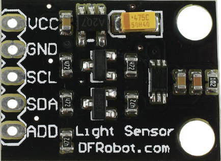
The BH1750 is a digital light sensor manufactured by Fermion (Part ID: SEN0097). It is designed to measure ambient light intensity in lux, providing precise and reliable readings. The sensor communicates via the I2C protocol, making it easy to integrate into microcontroller-based systems. Its compact design and low power consumption make it ideal for a wide range of applications.
Explore Projects Built with BH1750 Light Sensor
Explore Projects Built with BH1750 Light Sensor
Common Applications
- Automatic brightness control for displays (e.g., smartphones, TVs)
- Energy-efficient lighting systems
- Weather monitoring stations
- Smart home automation
- Agricultural light monitoring
Technical Specifications
The BH1750 offers high sensitivity and accuracy, making it suitable for various lighting conditions, from dim to bright environments.
Key Technical Details
| Parameter | Value |
|---|---|
| Operating Voltage | 2.4V to 3.6V |
| Typical Operating Voltage | 3.0V |
| Current Consumption | 0.12mA (typical) |
| Measurement Range | 1 lux to 65535 lux |
| Communication Protocol | I2C |
| I2C Address (Default) | 0x23 or 0x5C (configurable) |
| Resolution | 1 lux |
| Operating Temperature | -40°C to +85°C |
| Dimensions | 3.0mm x 1.6mm x 1.2mm |
Pin Configuration and Descriptions
The BH1750 sensor module typically includes six pins. Below is the pinout description:
| Pin Name | Description |
|---|---|
| VCC | Power supply input (2.4V to 3.6V) |
| GND | Ground |
| SDA | I2C data line |
| SCL | I2C clock line |
| ADDR | I2C address selection (connect to GND or VCC) |
| NC | Not connected (leave unconnected) |
I2C Address Selection
- ADDR connected to GND: I2C address is
0x23(default). - ADDR connected to VCC: I2C address is
0x5C.
Usage Instructions
The BH1750 is straightforward to use in a circuit, thanks to its I2C interface. Below are the steps to integrate and use the sensor:
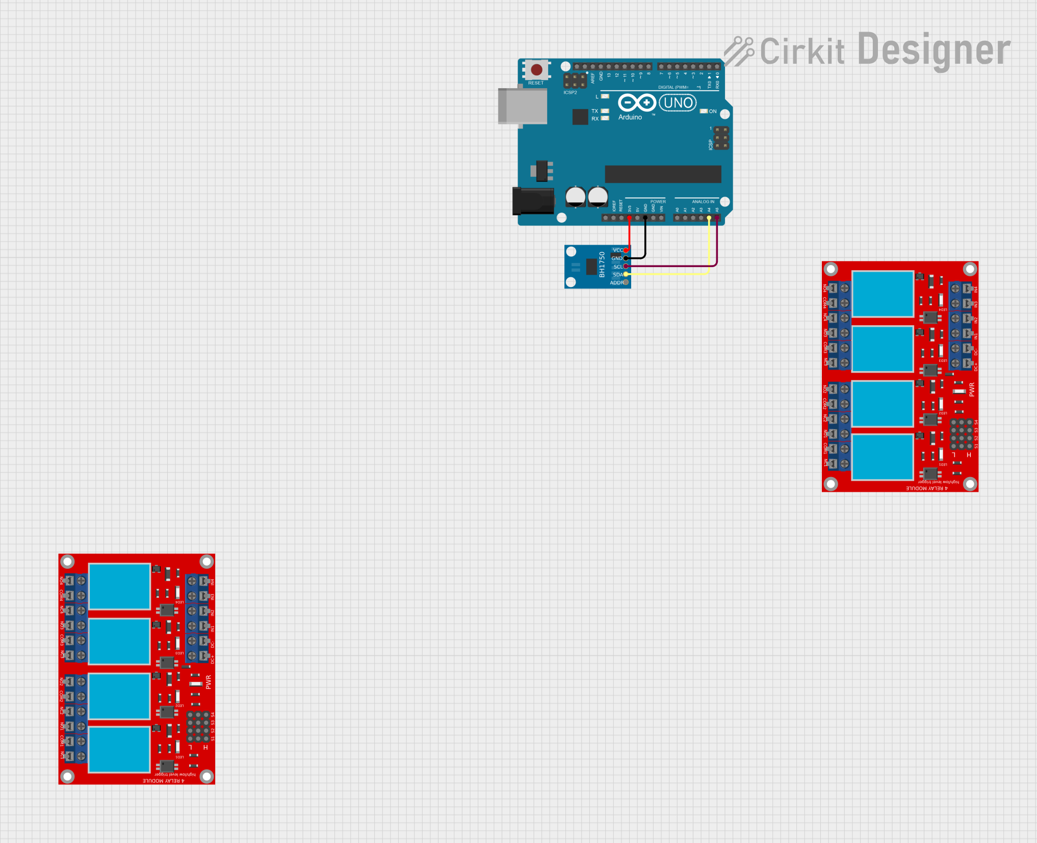
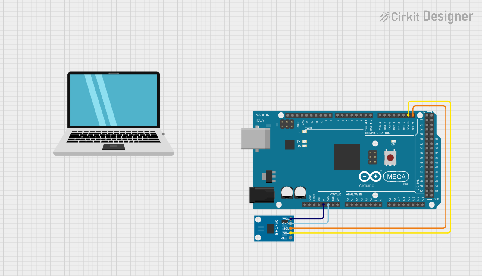
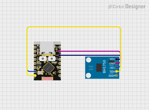
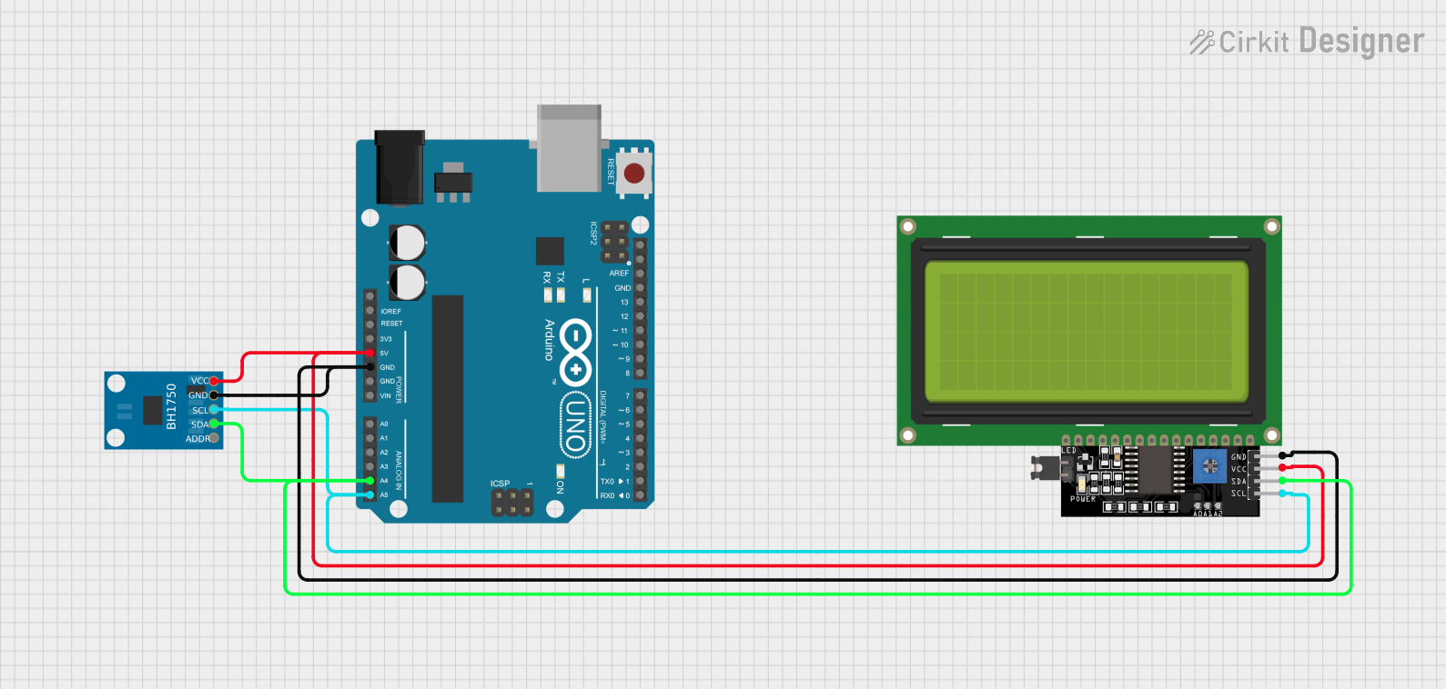
Connecting the BH1750 to an Arduino UNO
Wiring:
- Connect the VCC pin of the BH1750 to the 3.3V pin on the Arduino.
- Connect the GND pin of the BH1750 to the GND pin on the Arduino.
- Connect the SDA pin of the BH1750 to the A4 pin on the Arduino (I2C data line).
- Connect the SCL pin of the BH1750 to the A5 pin on the Arduino (I2C clock line).
- Optionally, connect the ADDR pin to GND or VCC to set the I2C address.
Install Required Library:
- Install the "BH1750" library in the Arduino IDE. Go to Sketch > Include Library > Manage Libraries, search for "BH1750", and install it.
Example Code: Use the following code to read light intensity from the BH1750:
#include <Wire.h>
#include <BH1750.h>

BH1750 lightMeter;

void setup() {
  Serial.begin(9600); // Initialize serial communication at 9600 baud
  Wire.begin();       // Initialize I2C communication

  if (lightMeter.begin()) {
    Serial.println("BH1750 initialized successfully");
  } else {
    Serial.println("Error initializing BH1750. Check wiring!");
    while (1); // Halt execution if initialization fails
  }
}

void loop() {
  float lux = lightMeter.readLightLevel(); // Read light intensity in lux

  if (lux >= 0) {
    Serial.print("Light Intensity: ");
    Serial.print(lux);
    Serial.println(" lux");
  } else {
    Serial.println("Error reading light level");
  }

  delay(1000); // Wait for 1 second before the next reading
}
Important Considerations
- Power Supply: Ensure the sensor operates within its voltage range (2.4V to 3.6V). Using 5V may damage the sensor.
- I2C Pull-Up Resistors: If your setup does not include pull-up resistors on the SDA and SCL lines, add 4.7kΩ resistors to ensure proper I2C communication.
- Ambient Light Conditions: Avoid placing the sensor in direct sunlight for extended periods, as it may affect accuracy.
Troubleshooting and FAQs
Common Issues and Solutions
No Data or Incorrect Readings:
- Cause: Incorrect wiring or I2C address mismatch.
- Solution: Double-check the wiring and ensure the correct I2C address is used in the code.
BH1750 Initialization Fails:
- Cause: Loose connections or insufficient power supply.
- Solution: Verify all connections and ensure the sensor is powered with 3.3V.
Fluctuating Readings:
- Cause: Electrical noise or unstable power supply.
- Solution: Use decoupling capacitors (e.g., 0.1µF) near the sensor's power pins.
Sensor Not Detected on I2C Bus:
- Cause: Incorrect I2C address or missing pull-up resistors.
- Solution: Check the ADDR pin configuration and add 4.7kΩ pull-up resistors if needed.
FAQs
Q1: Can the BH1750 measure light intensity in direct sunlight?
A1: Yes, the BH1750 can measure up to 65535 lux, but prolonged exposure to direct sunlight may reduce accuracy.
Q2: Can I use the BH1750 with a 5V microcontroller?
A2: Yes, but you must use a logic level shifter to step down the I2C signals to 3.3V to avoid damaging the sensor.
Q3: How do I change the measurement mode of the BH1750?
A3: The BH1750 supports multiple modes (e.g., high resolution, low resolution). Refer to the library documentation to configure the desired mode.
Q4: What is the typical response time of the BH1750?
A4: The response time depends on the measurement mode, typically ranging from 16ms to 120ms.
By following this documentation, you can effectively integrate and use the BH1750 light sensor in your projects.