How to Use Motor Controller: Examples, Pinouts, and Specs
Introduction
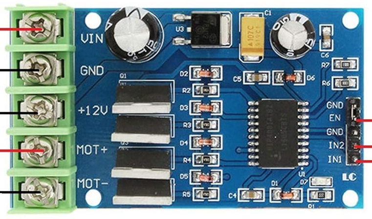
The NOYITO 170W High-power H-bridge Motor Drive Module 2-Channel is a versatile motor controller designed to regulate the speed, direction, and torque of electric motors. It achieves this by controlling the power supplied to the motor, making it ideal for a wide range of applications. This motor controller is based on an H-bridge design, which allows for efficient bidirectional control of DC motors.
Explore Projects Built with Motor Controller

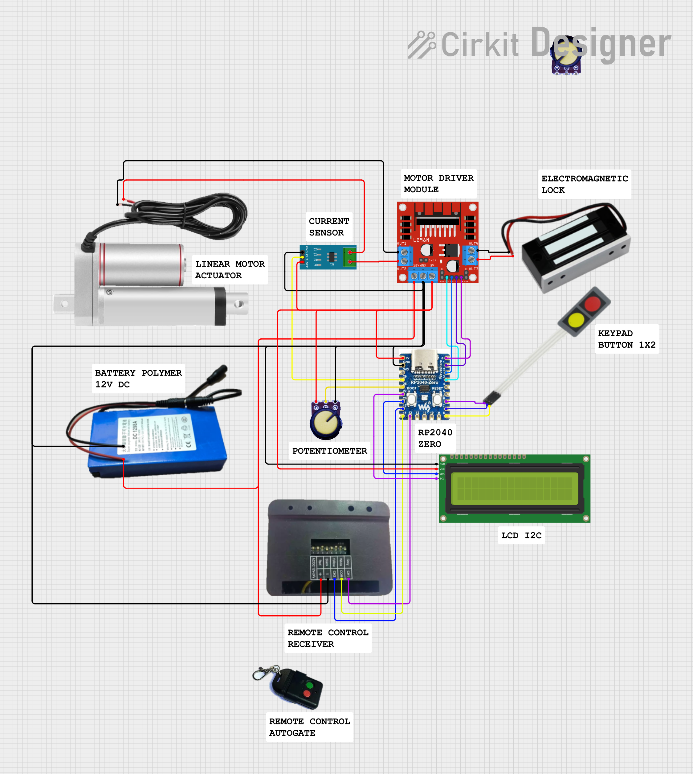
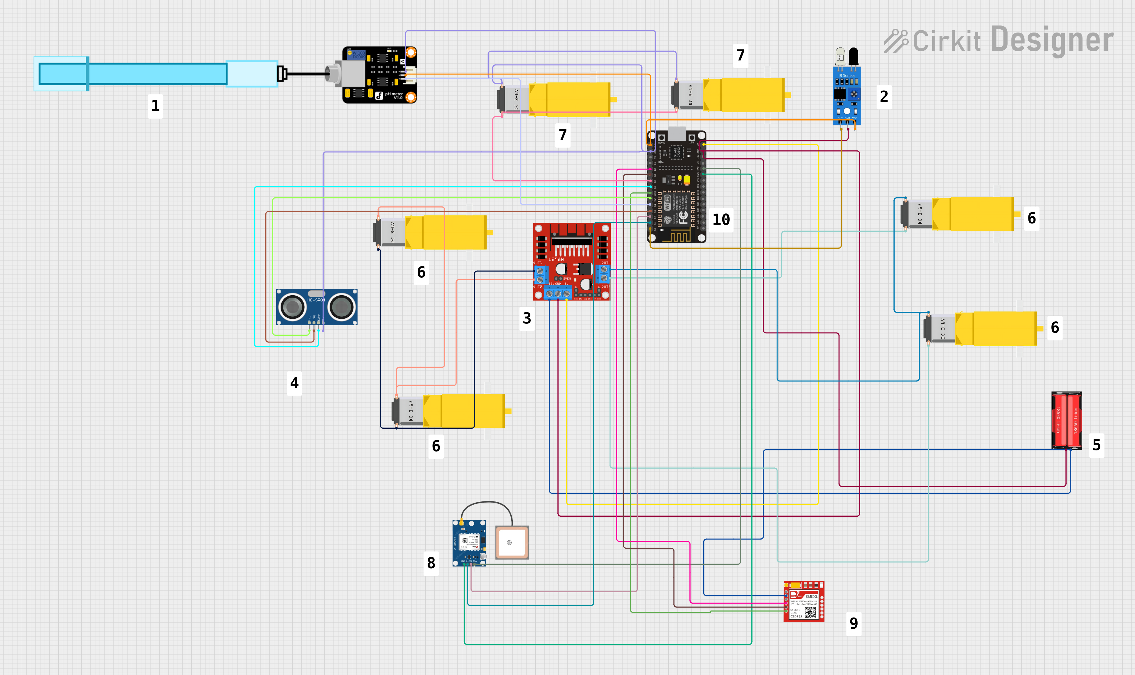
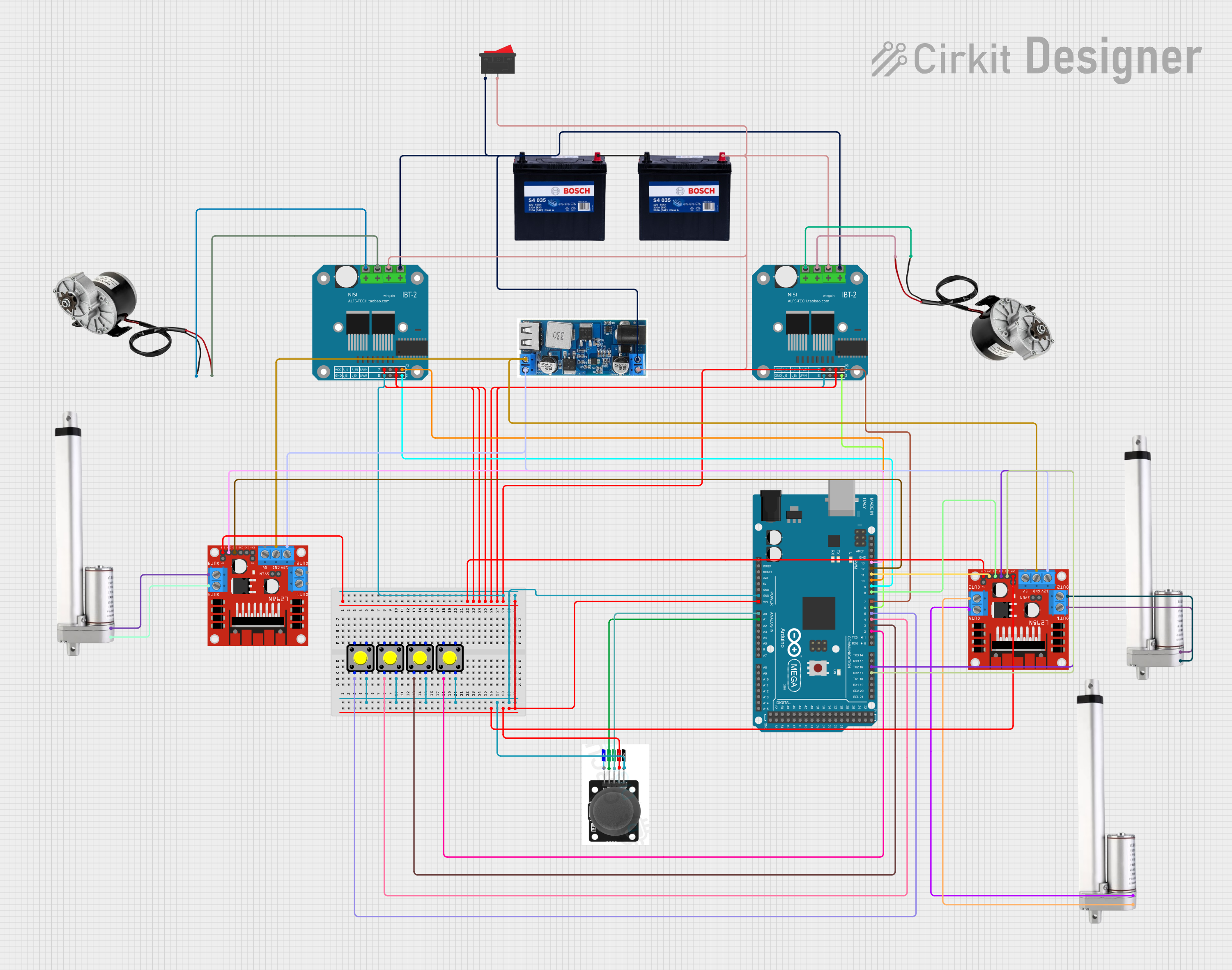
Explore Projects Built with Motor Controller
Common Applications and Use Cases
- Robotics: Controlling the movement of robot wheels or arms.
- Electric vehicles: Managing motor speed and direction.
- Conveyor belts: Adjusting speed and direction in industrial automation.
- DIY projects: Building motorized systems such as remote-controlled cars or drones.
Technical Specifications
The following table outlines the key technical details of the NOYITO 170W High-power H-bridge Motor Drive Module:
| Parameter | Specification |
|---|---|
| Operating Voltage | 6V to 27V DC |
| Maximum Output Power | 170W per channel |
| Continuous Current | 15A per channel |
| Peak Current | 30A per channel (short duration) |
| Number of Channels | 2 (independent control for two motors) |
| Control Logic Voltage | 3.3V to 5V (compatible with Arduino, etc.) |
| PWM Frequency | Up to 20 kHz |
| Dimensions | 60mm x 50mm x 20mm |
| Weight | 50g |
Pin Configuration and Descriptions
The module has the following pin layout:
| Pin Name | Description |
|---|---|
| VCC | Power input for the motor (6V to 27V DC). |
| GND | Ground connection. |
| INA1 | Input signal to control the direction of Motor 1. |
| INB1 | Input signal to control the direction of Motor 1 (complementary to INA1). |
| PWM1 | PWM input to control the speed of Motor 1. |
| INA2 | Input signal to control the direction of Motor 2. |
| INB2 | Input signal to control the direction of Motor 2 (complementary to INA2). |
| PWM2 | PWM input to control the speed of Motor 2. |
| OUT1A | Output terminal for Motor 1 (connect to one motor lead). |
| OUT1B | Output terminal for Motor 1 (connect to the other motor lead). |
| OUT2A | Output terminal for Motor 2 (connect to one motor lead). |
| OUT2B | Output terminal for Motor 2 (connect to the other motor lead). |
Usage Instructions
How to Use the Component in a Circuit
- Power Supply: Connect the VCC pin to a DC power source (6V to 27V) and the GND pin to ground.
- Motor Connections: Connect the motor leads to the OUT1A and OUT1B terminals for Motor 1, and OUT2A and OUT2B for Motor 2.
- Control Signals: Use a microcontroller (e.g., Arduino UNO) to send control signals to the INA, INB, and PWM pins for each motor:
- Set INA high and INB low to rotate the motor in one direction.
- Set INA low and INB high to rotate the motor in the opposite direction.
- Use the PWM pin to control the motor speed by varying the duty cycle of the PWM signal.
Important Considerations and Best Practices
- Ensure the power supply voltage matches the motor's operating voltage to avoid damage.
- Use heat sinks or cooling mechanisms if operating at high currents for extended periods.
- Avoid shorting the output terminals (OUT1A, OUT1B, OUT2A, OUT2B) to prevent damage to the module.
- Use appropriate decoupling capacitors near the power input to reduce noise and voltage spikes.
Example Code for Arduino UNO
Below is an example code snippet to control a single motor using the NOYITO motor controller:
// Define motor control pins
const int INA1 = 9;  // Direction control pin for Motor 1
const int INB1 = 8;  // Direction control pin for Motor 1
const int PWM1 = 10; // Speed control pin (PWM) for Motor 1

void setup() {
  // Set motor control pins as outputs
  pinMode(INA1, OUTPUT);
  pinMode(INB1, OUTPUT);
  pinMode(PWM1, OUTPUT);
}

void loop() {
  // Rotate motor in one direction at 50% speed
  digitalWrite(INA1, HIGH);  // Set direction
  digitalWrite(INB1, LOW);   // Set complementary direction
  analogWrite(PWM1, 128);    // Set speed (128/255 = 50% duty cycle)
  delay(2000);               // Run for 2 seconds

  // Stop the motor
  analogWrite(PWM1, 0);      // Set speed to 0
  delay(1000);               // Wait for 1 second

  // Rotate motor in the opposite direction at full speed
  digitalWrite(INA1, LOW);   // Set direction
  digitalWrite(INB1, HIGH);  // Set complementary direction
  analogWrite(PWM1, 255);    // Set speed (255/255 = 100% duty cycle)
  delay(2000);               // Run for 2 seconds

  // Stop the motor
  analogWrite(PWM1, 0);      // Set speed to 0
  delay(1000);               // Wait for 1 second
}
Troubleshooting and FAQs
Common Issues and Solutions
Motor Not Spinning:
- Cause: Incorrect wiring or insufficient power supply.
- Solution: Double-check all connections and ensure the power supply voltage matches the motor's requirements.
Motor Spins in the Wrong Direction:
- Cause: INA and INB signals are reversed.
- Solution: Swap the INA and INB signals or reverse the motor leads.
Overheating:
- Cause: Prolonged operation at high currents without proper cooling.
- Solution: Add a heat sink or cooling fan to the module.
PWM Signal Not Working:
- Cause: Incorrect PWM frequency or duty cycle.
- Solution: Ensure the PWM frequency is within the module's supported range (up to 20 kHz).
FAQs
Can I use this module with a 3.3V microcontroller? Yes, the control logic is compatible with both 3.3V and 5V systems.
What type of motors can I control with this module? This module is designed for DC motors with operating voltages between 6V and 27V.
Can I control two motors independently? Yes, the module has two independent channels for controlling two motors.
Is reverse polarity protection included? No, ensure correct polarity when connecting the power supply to avoid damage.