Cirkit Designer Logo
Cirkit Designer
Your all-in-one circuit design IDE
Home / 
Component Documentation

How to Use SP3232 TTL naar RS232: Examples, Pinouts, and Specs

Image of SP3232 TTL naar RS232
Cirkit Designer LogoDesign with SP3232 TTL naar RS232 in Cirkit Designer

Introduction

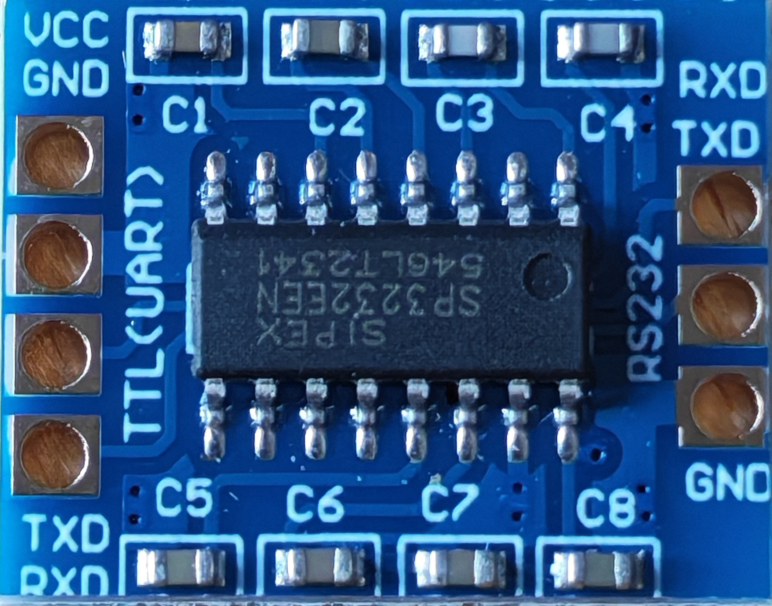
The SP3232 is a dual driver/receiver IC designed to convert TTL logic levels to RS-232 levels and vice versa. This makes it an essential component for enabling communication between microcontrollers (such as Arduino or other TTL-based devices) and RS-232 devices like computers, modems, or other serial communication equipment. The SP3232 is known for its low power consumption, wide operating voltage range, and compliance with RS-232 standards, making it a reliable choice for serial communication applications.

Explore Projects Built with SP3232 TTL naar RS232

Use Cirkit Designer to design, explore, and prototype these projects online. Some projects support real-time simulation. Click "Open Project" to start designing instantly!
Satellite Compass and Network-Integrated GPS Data Processing System
Image of GPS 시스템 측정 구성도_241016: A project utilizing SP3232 TTL naar RS232 in a practical application
This circuit comprises a satellite compass, a mini PC, two GPS antennas, power supplies, a network switch, media converters, and an atomic rubidium clock. The satellite compass is powered by a triple output DC power supply and interfaces with an RS232 splitter for 1PPS signals. The mini PCs are connected to the USRP B200 devices via USB for data and power, and to media converters via Ethernet, which in turn connect to a network switch using fiber optic links. The antennas are connected to the USRP B200s through RF directional couplers, and the atomic clock provides a 1PPS input to the RS232 splitter.
Cirkit Designer LogoOpen Project in Cirkit Designer
Arduino UNO and Relay-Controlled RS485 Communication System
Image of Diagrama: A project utilizing SP3232 TTL naar RS232 in a practical application
This circuit features an Arduino UNO microcontroller interfaced with a 4-channel relay module and a UART TTL to RS485 converter. The Arduino controls the relays via digital pins and communicates with the RS485 converter for serial communication, enabling control of external devices and communication over long distances.
Cirkit Designer LogoOpen Project in Cirkit Designer
Satellite-Based Timing and Navigation System with SDR and Atomic Clock Synchronization
Image of GPS 시스템 측정 구성도_Confirm: A project utilizing SP3232 TTL naar RS232 in a practical application
This circuit appears to be a complex system involving power supply management, GPS and timing synchronization, and data communication. It includes a SI-TEX G1 Satellite Compass for GPS data, an XHTF1021 Atomic Rubidium Clock for precise timing, and Ettus USRP B200 units for software-defined radio communication. Power is supplied through various SMPS units and distributed via terminal blocks and DC jacks. Data communication is facilitated by Beelink MINI S12 N95 computers, RS232 splitters, and a 1000BASE-T Media Converter for network connectivity. RF Directional Couplers are used to interface antennas with the USRP units, and the entire system is likely contained within cases for protection and organization.
Cirkit Designer LogoOpen Project in Cirkit Designer
ESP32C3-Based Soil Monitoring System with RS485 Communication
Image of 3-slave-soil: A project utilizing SP3232 TTL naar RS232 in a practical application
This circuit features an ESP32C3 Supermini microcontroller interfaced with an RS485 transceiver module, allowing for serial communication over long distances. A toggle switch and a pushbutton are connected to the ESP32C3 for user input, with a pull-up resistor on the toggle switch. Additionally, the circuit includes an NPK Soil Sensor connected to the RS485 module for measuring soil nutrient levels, with power supplied to the sensor and RS485 module from the ESP32C3.
Cirkit Designer LogoOpen Project in Cirkit Designer

Explore Projects Built with SP3232 TTL naar RS232

Use Cirkit Designer to design, explore, and prototype these projects online. Some projects support real-time simulation. Click "Open Project" to start designing instantly!
Image of GPS 시스템 측정 구성도_241016: A project utilizing SP3232 TTL naar RS232 in a practical application
Satellite Compass and Network-Integrated GPS Data Processing System
This circuit comprises a satellite compass, a mini PC, two GPS antennas, power supplies, a network switch, media converters, and an atomic rubidium clock. The satellite compass is powered by a triple output DC power supply and interfaces with an RS232 splitter for 1PPS signals. The mini PCs are connected to the USRP B200 devices via USB for data and power, and to media converters via Ethernet, which in turn connect to a network switch using fiber optic links. The antennas are connected to the USRP B200s through RF directional couplers, and the atomic clock provides a 1PPS input to the RS232 splitter.
Cirkit Designer LogoOpen Project in Cirkit Designer
Image of Diagrama: A project utilizing SP3232 TTL naar RS232 in a practical application
Arduino UNO and Relay-Controlled RS485 Communication System
This circuit features an Arduino UNO microcontroller interfaced with a 4-channel relay module and a UART TTL to RS485 converter. The Arduino controls the relays via digital pins and communicates with the RS485 converter for serial communication, enabling control of external devices and communication over long distances.
Cirkit Designer LogoOpen Project in Cirkit Designer
Image of GPS 시스템 측정 구성도_Confirm: A project utilizing SP3232 TTL naar RS232 in a practical application
Satellite-Based Timing and Navigation System with SDR and Atomic Clock Synchronization
This circuit appears to be a complex system involving power supply management, GPS and timing synchronization, and data communication. It includes a SI-TEX G1 Satellite Compass for GPS data, an XHTF1021 Atomic Rubidium Clock for precise timing, and Ettus USRP B200 units for software-defined radio communication. Power is supplied through various SMPS units and distributed via terminal blocks and DC jacks. Data communication is facilitated by Beelink MINI S12 N95 computers, RS232 splitters, and a 1000BASE-T Media Converter for network connectivity. RF Directional Couplers are used to interface antennas with the USRP units, and the entire system is likely contained within cases for protection and organization.
Cirkit Designer LogoOpen Project in Cirkit Designer
Image of 3-slave-soil: A project utilizing SP3232 TTL naar RS232 in a practical application
ESP32C3-Based Soil Monitoring System with RS485 Communication
This circuit features an ESP32C3 Supermini microcontroller interfaced with an RS485 transceiver module, allowing for serial communication over long distances. A toggle switch and a pushbutton are connected to the ESP32C3 for user input, with a pull-up resistor on the toggle switch. Additionally, the circuit includes an NPK Soil Sensor connected to the RS485 module for measuring soil nutrient levels, with power supplied to the sensor and RS485 module from the ESP32C3.
Cirkit Designer LogoOpen Project in Cirkit Designer

Common Applications and Use Cases

  • Interfacing microcontrollers with RS-232 devices
  • Serial communication in embedded systems
  • Data logging and monitoring systems
  • Industrial automation and control systems
  • Debugging and programming microcontrollers via RS-232

Technical Specifications

The SP3232 is designed to meet the requirements of modern serial communication systems. Below are its key technical details:

Key Technical Details

  • Operating Voltage: 3.0V to 5.5V
  • Data Rate: Up to 250 kbps
  • Number of Drivers/Receivers: 2 drivers, 2 receivers
  • RS-232 Output Voltage Levels: ±5V to ±15V
  • TTL Input Voltage Levels: 0V to Vcc
  • Low Power Consumption: 1 µA in shutdown mode
  • ESD Protection: ±15 kV (Human Body Model)
  • Operating Temperature Range: -40°C to +85°C
  • Package Types: SOIC, TSSOP

Pin Configuration and Descriptions

The SP3232 typically comes in a 16-pin package. Below is the pin configuration and description:

Pin Number Pin Name Description
1 C1+ Positive terminal of the external charge pump capacitor
2 V+ Positive voltage generated by the charge pump
3 C1- Negative terminal of the external charge pump capacitor
4 C2+ Positive terminal of the second charge pump capacitor
5 C2- Negative terminal of the second charge pump capacitor
6 V- Negative voltage generated by the charge pump
7 T2OUT RS-232 Transmitter Output 2
8 R2IN RS-232 Receiver Input 2
9 R2OUT TTL Receiver Output 2
10 T2IN TTL Transmitter Input 2
11 T1IN TTL Transmitter Input 1
12 R1OUT TTL Receiver Output 1
13 R1IN RS-232 Receiver Input 1
14 T1OUT RS-232 Transmitter Output 1
15 GND Ground
16 Vcc Supply Voltage (3.0V to 5.5V)

Usage Instructions

The SP3232 is straightforward to use in circuits for TTL to RS-232 level conversion. Below are the steps and considerations for using the component effectively:

How to Use the SP3232 in a Circuit

  1. Power Supply: Connect the Vcc pin to a 3.0V to 5.5V power source and the GND pin to ground.
  2. Charge Pump Capacitors: Connect external capacitors (typically 0.1 µF to 1 µF) between the charge pump pins (C1+, C1-, C2+, C2-, V+, and V-). These capacitors are required for the internal voltage conversion circuitry.
  3. TTL Connections: Connect the TTL logic signals from your microcontroller to the T1IN and T2IN pins for transmission, and receive TTL signals on the R1OUT and R2OUT pins.
  4. RS-232 Connections: Connect the RS-232 device to the T1OUT and T2OUT pins for transmission, and receive RS-232 signals on the R1IN and R2IN pins.
  5. Bypass Capacitor: Place a 0.1 µF decoupling capacitor close to the Vcc pin to stabilize the power supply.

Important Considerations and Best Practices

  • Ensure the external capacitors are of the correct value and placed as close as possible to the IC to ensure proper charge pump operation.
  • Avoid exceeding the maximum voltage ratings for the Vcc and RS-232 pins to prevent damage to the IC.
  • Use proper ESD protection when handling the IC to avoid damage from static discharge.
  • If using the SP3232 with an Arduino UNO, ensure the Arduino's 5V logic levels are compatible with the SP3232's TTL inputs.

Example: Connecting SP3232 to an Arduino UNO

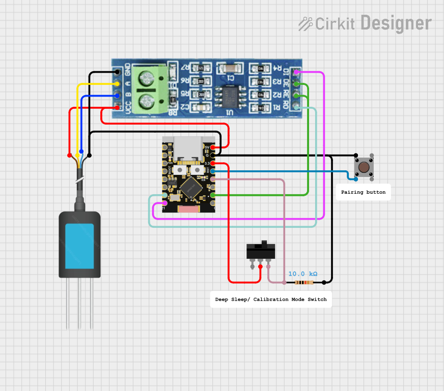
Below is an example of how to connect the SP3232 to an Arduino UNO for serial communication with an RS-232 device:

Circuit Diagram

  • Connect the Arduino's TX pin to the SP3232's T1IN pin.
  • Connect the Arduino's RX pin to the SP3232's R1OUT pin.
  • Connect the SP3232's T1OUT and R1IN pins to the RS-232 device.

Arduino Code Example

// Example code for using SP3232 with Arduino UNO
// This code sends and receives data over RS-232 using the SP3232

void setup() {
  Serial.begin(9600); // Initialize serial communication at 9600 baud
  Serial.println("SP3232 RS-232 Communication Test");
}

void loop() {
  // Check if data is available from the RS-232 device
  if (Serial.available() > 0) {
    char receivedData = Serial.read(); // Read the incoming data
    Serial.print("Received: ");
    Serial.println(receivedData); // Print the received data
  }

  // Send data to the RS-232 device
  Serial.println("Hello RS-232 Device!");
  delay(1000); // Wait for 1 second before sending the next message
}

Troubleshooting and FAQs

Common Issues and Solutions

  1. No Communication Between Devices

    • Cause: Incorrect wiring or missing charge pump capacitors.
    • Solution: Double-check all connections and ensure the capacitors are properly connected.
  2. Data Corruption

    • Cause: Mismatched baud rates between the microcontroller and RS-232 device.
    • Solution: Ensure both devices are configured to use the same baud rate.
  3. SP3232 Overheating

    • Cause: Exceeding the maximum voltage ratings or incorrect capacitor values.
    • Solution: Verify the power supply voltage and capacitor values.
  4. No Output on RS-232 Side

    • Cause: Faulty or missing external capacitors.
    • Solution: Replace or add the required capacitors for the charge pump.

FAQs

Q: Can the SP3232 operate at 3.3V?
A: Yes, the SP3232 can operate at voltages as low as 3.0V, making it compatible with 3.3V systems.

Q: What is the maximum cable length for RS-232 communication?
A: The RS-232 standard supports cable lengths up to 15 meters (50 feet) at lower baud rates. However, shorter cables are recommended for higher baud rates to avoid signal degradation.

Q: Do I need external pull-up resistors for the TTL pins?
A: No, the SP3232 does not require external pull-up resistors for its TTL pins.

Q: Can I use the SP3232 for bidirectional communication?
A: Yes, the SP3232 supports bidirectional communication with its dual driver/receiver configuration.