Cirkit Designer Logo
Cirkit Designer
Your all-in-one circuit design IDE
Home / 
Component Documentation

How to Use STM32 Nucleo-144 boards: Examples, Pinouts, and Specs

Image of STM32 Nucleo-144 boards
Cirkit Designer LogoDesign with STM32 Nucleo-144 boards in Cirkit Designer

Introduction

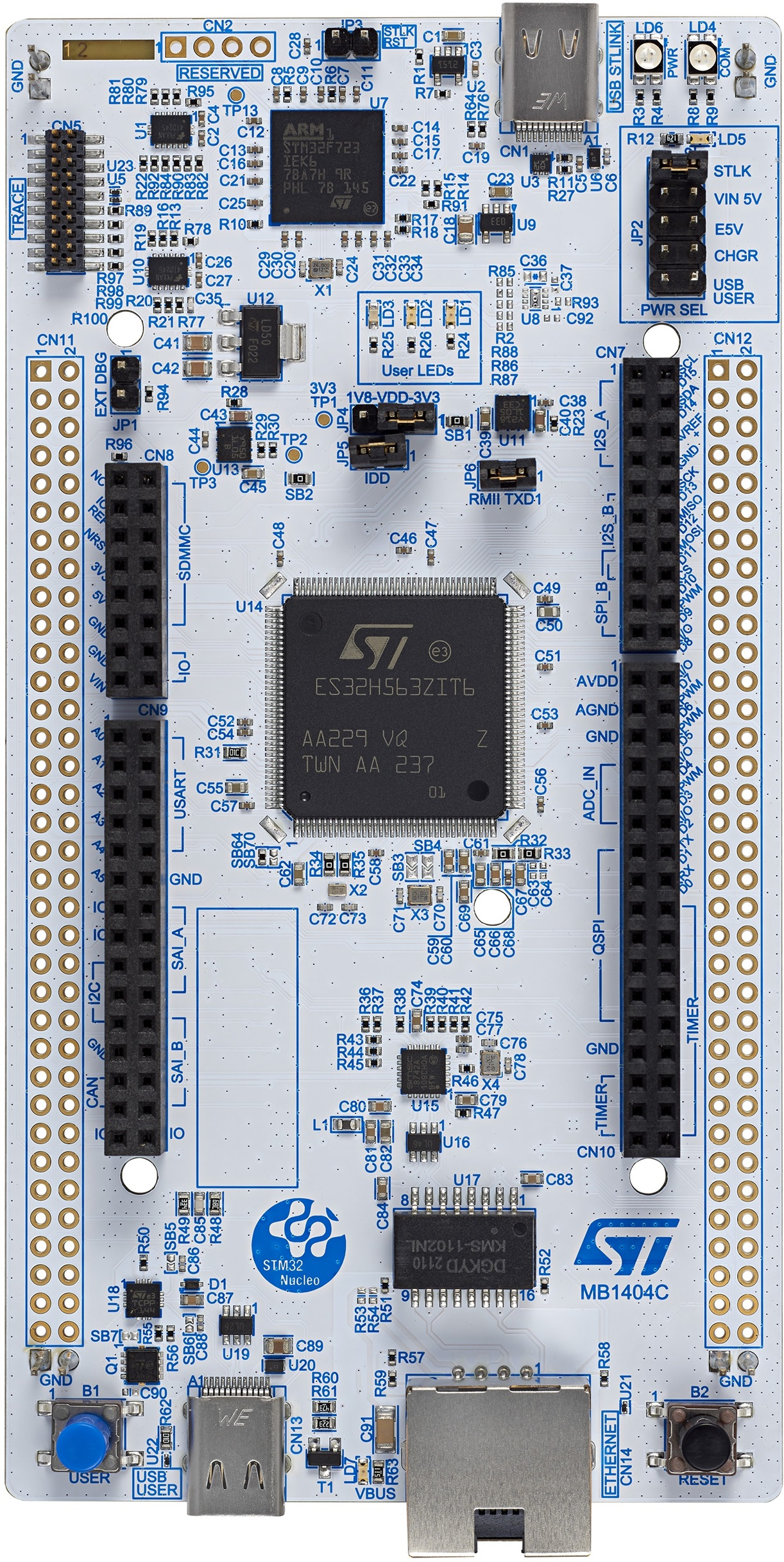
The STM32 Nucleo-144 boards, manufactured by STMicroelectronics, are versatile development boards designed to simplify prototyping and application development using STM32 microcontrollers. The NUCLEO-H563ZI model features the STM32H563ZI microcontroller, which is based on the high-performance Arm® Cortex®-M33 core. These boards offer a wide range of connectivity options, a large number of GPIO pins, and compatibility with Arduino™, ST Zio, and Morpho expansion connectors.

Explore Projects Built with STM32 Nucleo-144 boards

Use Cirkit Designer to design, explore, and prototype these projects online. Some projects support real-time simulation. Click "Open Project" to start designing instantly!
STM32 Nucleo F303RE Controlled Ultrasonic Sensing with RGB Feedback and I2C LCD Display
Image of CS435-final: A project utilizing STM32 Nucleo-144 boards in a practical application
This circuit features a STM32 Nucleo F303RE microcontroller interfaced with three HC-SR04 ultrasonic sensors for distance measurement and a 20x4 LCD display over I2C for data output. Additionally, there is a WS2812 RGB LED strip controlled by the microcontroller for visual feedback. The power supply provides a common 5V to the LCD, ultrasonic sensors, LED strip, and the microcontroller's +5V input, with all components sharing a common ground.
Cirkit Designer LogoOpen Project in Cirkit Designer
WiFi-Enabled Environmental Monitoring System with Alert Notifications
Image of GAS LEAKAGE DETECTION: A project utilizing STM32 Nucleo-144 boards in a practical application
This circuit features a NUCLEO-F303RE microcontroller board interfaced with several modules for sensing, actuation, and communication. It uses I2C communication to display data on an LCD screen, UART communication to interface with an ESP8266 WiFi module, and reads an MQ-2 gas sensor via an ADC pin. The microcontroller also controls a buzzer for audible alerts and a relay module for switching higher power loads, possibly in response to sensor readings or remote commands received over WiFi.
Cirkit Designer LogoOpen Project in Cirkit Designer
STM32F4-Based Multi-Sensor GPS Tracking System
Image of Phase 1 fc: A project utilizing STM32 Nucleo-144 boards in a practical application
This circuit integrates an STM32F4 microcontroller with a GPS module (NEO 6M), an accelerometer and gyroscope (MPU-6050), a barometric pressure sensor (BMP280), and a compass (HMC5883L). The microcontroller communicates with the sensors via I2C and the GPS module via UART, enabling it to gather and process environmental and positional data.
Cirkit Designer LogoOpen Project in Cirkit Designer
STM32 and Arduino Pro Mini Based Wireless Data Logger with OLED Display
Image of R8 Controller V1: A project utilizing STM32 Nucleo-144 boards in a practical application
This circuit integrates multiple microcontrollers (Maple Mini STM32F1, nRF52840 ProMicro, and Arduino Pro Mini) to interface with various peripherals including an SSD1306 OLED display, an SD card module, and a Si4463 RF module. The circuit is designed for data acquisition, storage, and wireless communication, with power supplied through a USB Serial TTL module.
Cirkit Designer LogoOpen Project in Cirkit Designer

Explore Projects Built with STM32 Nucleo-144 boards

Use Cirkit Designer to design, explore, and prototype these projects online. Some projects support real-time simulation. Click "Open Project" to start designing instantly!
Image of CS435-final: A project utilizing STM32 Nucleo-144 boards in a practical application
STM32 Nucleo F303RE Controlled Ultrasonic Sensing with RGB Feedback and I2C LCD Display
This circuit features a STM32 Nucleo F303RE microcontroller interfaced with three HC-SR04 ultrasonic sensors for distance measurement and a 20x4 LCD display over I2C for data output. Additionally, there is a WS2812 RGB LED strip controlled by the microcontroller for visual feedback. The power supply provides a common 5V to the LCD, ultrasonic sensors, LED strip, and the microcontroller's +5V input, with all components sharing a common ground.
Cirkit Designer LogoOpen Project in Cirkit Designer
Image of GAS LEAKAGE DETECTION: A project utilizing STM32 Nucleo-144 boards in a practical application
WiFi-Enabled Environmental Monitoring System with Alert Notifications
This circuit features a NUCLEO-F303RE microcontroller board interfaced with several modules for sensing, actuation, and communication. It uses I2C communication to display data on an LCD screen, UART communication to interface with an ESP8266 WiFi module, and reads an MQ-2 gas sensor via an ADC pin. The microcontroller also controls a buzzer for audible alerts and a relay module for switching higher power loads, possibly in response to sensor readings or remote commands received over WiFi.
Cirkit Designer LogoOpen Project in Cirkit Designer
Image of Phase 1 fc: A project utilizing STM32 Nucleo-144 boards in a practical application
STM32F4-Based Multi-Sensor GPS Tracking System
This circuit integrates an STM32F4 microcontroller with a GPS module (NEO 6M), an accelerometer and gyroscope (MPU-6050), a barometric pressure sensor (BMP280), and a compass (HMC5883L). The microcontroller communicates with the sensors via I2C and the GPS module via UART, enabling it to gather and process environmental and positional data.
Cirkit Designer LogoOpen Project in Cirkit Designer
Image of R8 Controller V1: A project utilizing STM32 Nucleo-144 boards in a practical application
STM32 and Arduino Pro Mini Based Wireless Data Logger with OLED Display
This circuit integrates multiple microcontrollers (Maple Mini STM32F1, nRF52840 ProMicro, and Arduino Pro Mini) to interface with various peripherals including an SSD1306 OLED display, an SD card module, and a Si4463 RF module. The circuit is designed for data acquisition, storage, and wireless communication, with power supplied through a USB Serial TTL module.
Cirkit Designer LogoOpen Project in Cirkit Designer

Common Applications and Use Cases

  • Industrial control systems
  • IoT (Internet of Things) devices
  • Robotics and automation
  • Signal processing and data acquisition
  • Prototyping for consumer electronics
  • Educational and research projects

Technical Specifications

Key Technical Details

  • Microcontroller: STM32H563ZI (Arm® Cortex®-M33 core, 32-bit)
  • Operating Voltage: 3.3V (core), 5V (I/O compatibility)
  • Clock Speed: Up to 250 MHz
  • Flash Memory: 2 MB
  • SRAM: 640 KB
  • GPIO Pins: 144 pins (extensive I/O capabilities)
  • Connectivity:
    • USB Type-C® (for power and communication)
    • Ethernet (10/100 Mbps)
    • CAN, UART, SPI, I2C, and more
  • Expansion Connectors:
    • Arduino™ Uno V3 compatibility
    • ST Zio and Morpho connectors
  • Debugging: Integrated ST-LINK/V3 debugger/programmer
  • Power Supply: USB Type-C® or external power supply (7V–12V)
  • Dimensions: 102 mm x 102 mm

Pin Configuration and Descriptions

The STM32 Nucleo-144 boards feature multiple connectors for GPIO and peripherals. Below is a summary of the key pin configurations:

Arduino™ Uno V3 Connector

Pin Name Functionality Description
A0–A5 Analog Inputs 6 analog input pins
D0–D13 Digital I/O 14 digital I/O pins
3.3V Power Output 3.3V power supply
5V Power Output 5V power supply
GND Ground Common ground
VIN Power Input External power input (7V–12V)

ST Zio Connector

Pin Name Functionality Description
ZIO1–ZIO40 GPIO, Analog, Power Extended I/O and power connections

Morpho Connector

Pin Name Functionality Description
P1–P144 GPIO, Power, Debug Full access to STM32H563ZI pins

Usage Instructions

How to Use the Component in a Circuit

  1. Powering the Board:

    • Connect the board to your computer using a USB Type-C® cable for power and communication.
    • Alternatively, use an external power supply (7V–12V) via the VIN pin or dedicated power connector.
  2. Programming the Board:

    • Use the integrated ST-LINK/V3 debugger/programmer to upload firmware.
    • Compatible with popular IDEs such as STM32CubeIDE, Keil MDK, and IAR Embedded Workbench.
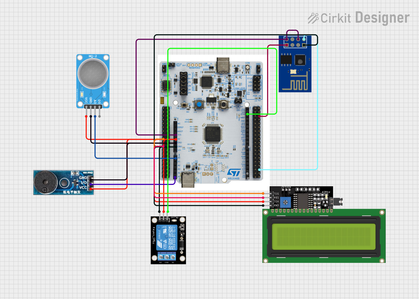
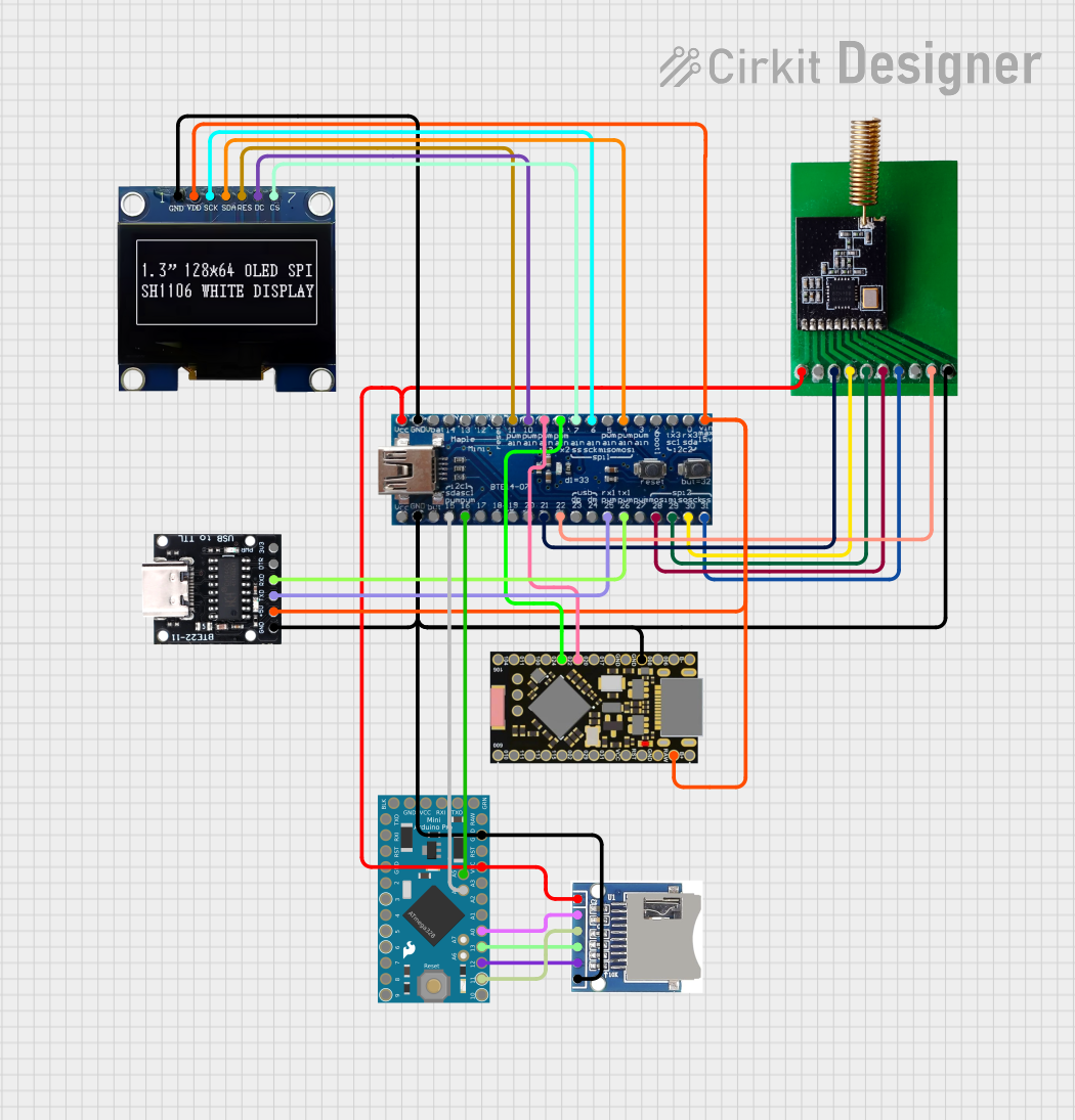
  3. Connecting Peripherals:

    • Use the Arduino™, ST Zio, or Morpho connectors to interface with sensors, actuators, and other peripherals.
    • Ensure proper voltage levels and pin configurations for connected devices.
  4. Running the Application:

    • After programming, reset the board using the reset button to execute the uploaded firmware.

Important Considerations and Best Practices

  • Power Supply: Ensure the board is powered within the specified voltage range to avoid damage.
  • Pin Protection: Avoid exceeding the maximum current ratings for GPIO pins (typically 25 mA per pin).
  • Debugging: Use the ST-LINK/V3 interface for efficient debugging and programming.
  • Firmware Updates: Regularly update the STM32Cube firmware package for the latest features and bug fixes.

Example Code for Arduino™ IDE

The STM32 Nucleo-144 boards can be programmed using the Arduino™ IDE. Below is an example of blinking an LED connected to pin D13:

// Example: Blink an LED on pin D13
// This code toggles the LED state every 500 milliseconds.

#define LED_PIN 13  // Define the LED pin (D13 on Arduino connector)

void setup() {
  pinMode(LED_PIN, OUTPUT);  // Set the LED pin as an output
}

void loop() {
  digitalWrite(LED_PIN, HIGH);  // Turn the LED on
  delay(500);                   // Wait for 500 milliseconds
  digitalWrite(LED_PIN, LOW);   // Turn the LED off
  delay(500);                   // Wait for 500 milliseconds
}

Troubleshooting and FAQs

Common Issues and Solutions

  1. Board Not Detected by Computer:

    • Ensure the USB Type-C® cable is properly connected.
    • Verify that the ST-LINK/V3 drivers are installed on your computer.
  2. Program Upload Fails:

    • Check the power supply and ensure the board is powered on.
    • Verify that the correct board and port are selected in your IDE.
  3. Peripheral Not Responding:

    • Double-check the pin connections and configurations.
    • Ensure the peripheral is powered and compatible with the board's voltage levels.
  4. LED Not Blinking in Example Code:

    • Confirm that the LED is connected to pin D13.
    • Verify that the uploaded code matches the example provided.

FAQs

  • Q: Can I use the STM32 Nucleo-144 boards with other IDEs?

    • A: Yes, the boards are compatible with STM32CubeIDE, Keil MDK, IAR Embedded Workbench, and more.
  • Q: What is the maximum current output of the GPIO pins?

    • A: Each GPIO pin can source or sink up to 25 mA.
  • Q: Can I power the board using a battery?

    • A: Yes, you can use a battery with a voltage range of 7V–12V connected to the VIN pin.
  • Q: Is the board compatible with Arduino™ shields?

    • A: Yes, the board supports Arduino™ Uno V3 shields via the Arduino™ connector.

This documentation provides a comprehensive guide to using the STM32 Nucleo-144 boards for your embedded development projects.