How to Use Cinch socket white: Examples, Pinouts, and Specs
Introduction
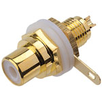
The Cinch socket, also known as an RCA socket, is a widely used connector for audio and video signals. The white color typically indicates the left audio channel in stereo setups. This component is essential in various audio-visual applications, including home theater systems, audio equipment, and video devices.
Explore Projects Built with Cinch socket white

Explore Projects Built with Cinch socket white
Common Applications and Use Cases
- Home Theater Systems: Connecting audio and video components such as DVD players, TVs, and speakers.
- Audio Equipment: Used in amplifiers, mixers, and other audio devices to transmit audio signals.
- Video Devices: Connecting video sources like camcorders and gaming consoles to displays.
- DIY Electronics Projects: Ideal for custom audio and video projects, including those involving microcontrollers like the Arduino UNO.
Technical Specifications
Key Technical Details
| Parameter | Value |
|---|---|
| Connector Type | RCA (Cinch) |
| Color | White |
| Channel | Left Audio |
| Voltage Rating | 12V DC (typical) |
| Current Rating | 1A (typical) |
| Material | Metal (contacts), Plastic (housing) |
| Mounting Type | Panel Mount |
Pin Configuration and Descriptions
| Pin Number | Description | Function |
|---|---|---|
| 1 | Signal (Center Pin) | Carries the audio signal |
| 2 | Ground (Outer Shell) | Provides the ground connection |
Usage Instructions
How to Use the Component in a Circuit
Mounting the Socket:
- Secure the Cinch socket to your panel or enclosure using the provided mounting hardware.
- Ensure the socket is firmly in place to prevent any movement or disconnection.
Wiring the Socket:
- Connect the center pin (Signal) to the audio signal source or input.
- Connect the outer shell (Ground) to the ground of your circuit.
Connecting to an Arduino UNO:
- Use a 3.5mm to RCA cable to connect the audio output of your Arduino project to the Cinch socket.
- Ensure proper grounding to avoid noise and interference.
Important Considerations and Best Practices
- Polarity: Always ensure correct polarity when connecting the signal and ground pins.
- Shielding: Use shielded cables to minimize noise and interference, especially in audio applications.
- Secure Connections: Ensure all connections are secure to prevent signal loss or degradation.
- Voltage and Current Ratings: Do not exceed the specified voltage and current ratings to avoid damage to the component.
Troubleshooting and FAQs
Common Issues Users Might Face
No Audio Signal:
- Solution: Check all connections to ensure they are secure and correctly wired. Verify that the audio source is functioning properly.
Noise or Interference:
- Solution: Use shielded cables and ensure proper grounding. Check for any nearby sources of electromagnetic interference.
Loose Connection:
- Solution: Ensure the Cinch socket is firmly mounted and all connections are tight. Use locking connectors if available.
FAQs
Q1: Can I use the Cinch socket for video signals?
- A1: Yes, Cinch sockets can be used for video signals, but the white color typically indicates it is for the left audio channel. For video, use the yellow Cinch socket.
Q2: What is the maximum cable length I can use with the Cinch socket?
- A2: The maximum cable length depends on the quality of the cable and the signal strength. For audio signals, it is generally recommended to keep the cable length under 20 meters to avoid signal degradation.
Q3: Can I connect the Cinch socket directly to an Arduino UNO?
- A3: Yes, you can connect the Cinch socket to an Arduino UNO using appropriate cables and ensuring proper grounding. Below is an example code to generate a simple audio signal using the Arduino UNO:
/*
 * Simple Audio Signal Generation
 * This code generates a simple square wave audio signal on pin 9.
 * Connect pin 9 to the signal pin of the Cinch socket.
 */

const int audioPin = 9; // Pin connected to the Cinch socket signal pin

void setup() {
  pinMode(audioPin, OUTPUT); // Set the audio pin as an output
}

void loop() {
  digitalWrite(audioPin, HIGH); // Set the pin high
  delayMicroseconds(500); // Wait for 500 microseconds
  digitalWrite(audioPin, LOW); // Set the pin low
  delayMicroseconds(500); // Wait for 500 microseconds
}
This code generates a simple square wave audio signal on pin 9 of the Arduino UNO. Connect pin 9 to the signal pin of the Cinch socket and the ground of the Arduino to the ground pin of the Cinch socket.
By following this documentation, users can effectively utilize the Cinch socket in their audio and video projects, ensuring reliable and high-quality connections.