How to Use Audio Amplifier: Examples, Pinouts, and Specs
Introduction
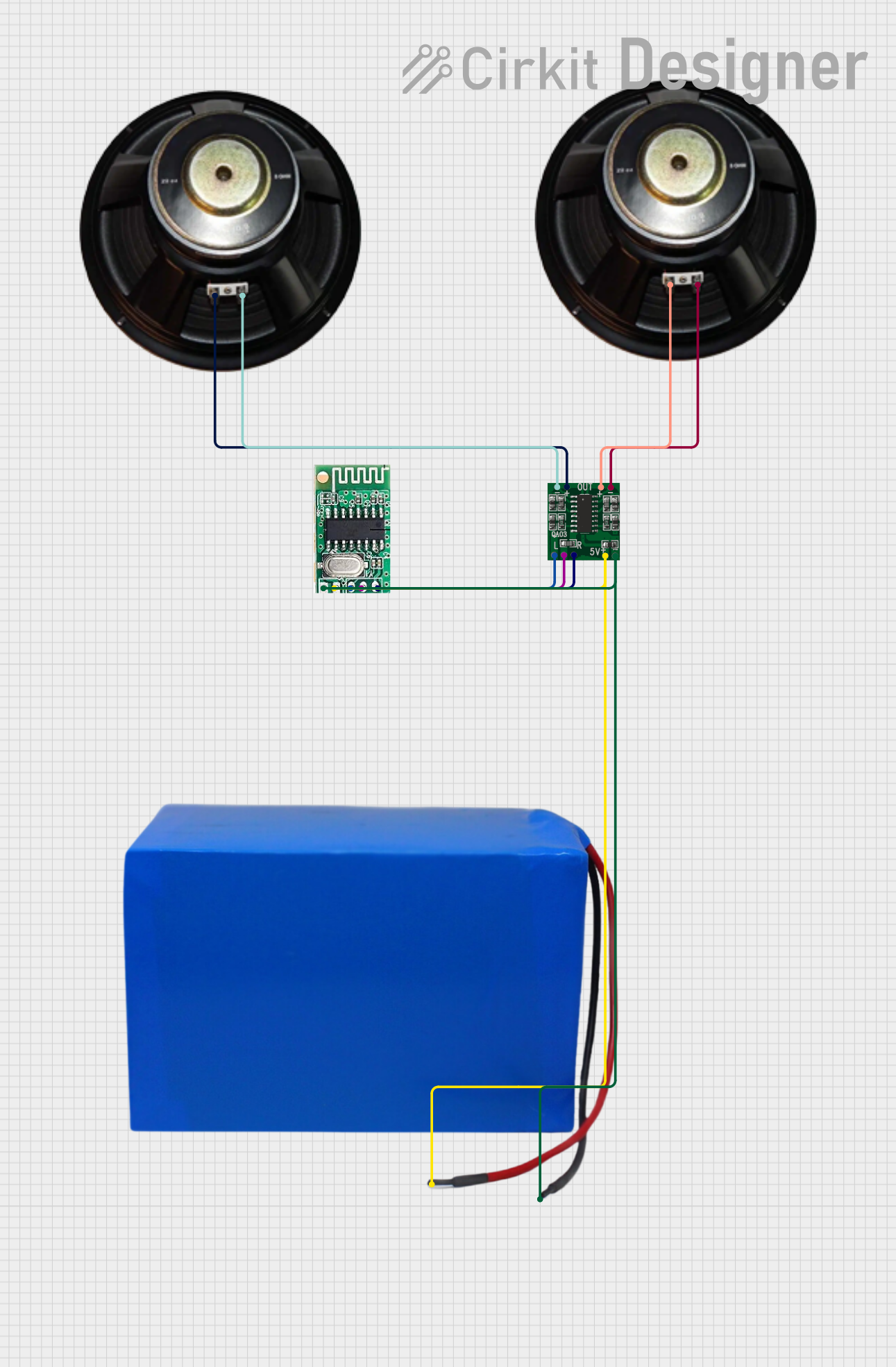
An audio amplifier is an electronic device designed to increase the amplitude of audio signals, enabling louder sound output through speakers or headphones. It is a critical component in audio systems, ensuring that weak audio signals from sources like microphones, musical instruments, or playback devices are amplified to drive output devices effectively. Audio amplifiers are widely used in home theater systems, portable speakers, musical equipment, and public address systems.
Explore Projects Built with Audio Amplifier
Explore Projects Built with Audio Amplifier
Technical Specifications
Below are the general technical specifications for a typical audio amplifier. Note that specific values may vary depending on the model and manufacturer.
General Specifications
- Input Voltage Range: 5V to 24V (depending on the amplifier type)
- Output Power: 1W to 100W or more (depending on the design)
- Frequency Response: 20 Hz to 20 kHz (standard for audio applications)
- Input Impedance: 10 kΩ to 100 kΩ
- Output Impedance: Typically 4Ω, 6Ω, or 8Ω (matches speaker impedance)
- Signal-to-Noise Ratio (SNR): ≥ 80 dB
- Total Harmonic Distortion (THD): ≤ 0.1%
Pin Configuration and Descriptions
The pin configuration of an audio amplifier IC (e.g., LM386) is as follows:
| Pin Number | Pin Name | Description |
|---|---|---|
| 1 | Gain | Used to set the gain of the amplifier (connect to a capacitor for higher gain). |
| 2 | Inverting Input (-) | Negative input terminal for the audio signal. |
| 3 | Non-Inverting Input (+) | Positive input terminal for the audio signal. |
| 4 | Ground (GND) | Ground connection for the circuit. |
| 5 | Output | Amplified audio signal output. |
| 6 | Vcc | Positive power supply input. |
| 7 | Bypass | Optional pin for bypassing noise (connect to a capacitor). |
| 8 | Gain | Used in conjunction with Pin 1 to set the gain. |
Usage Instructions
How to Use the Component in a Circuit
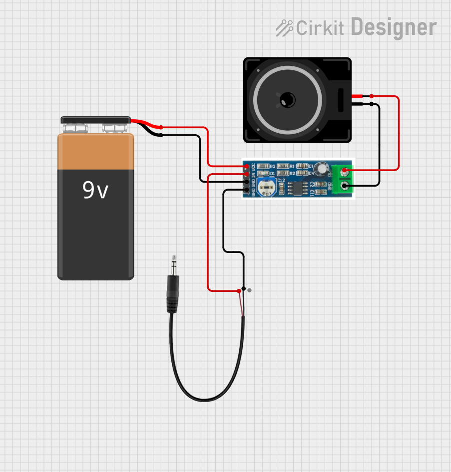
- Power Supply: Connect the Vcc pin to a suitable power source (e.g., 9V for LM386) and the GND pin to the ground.
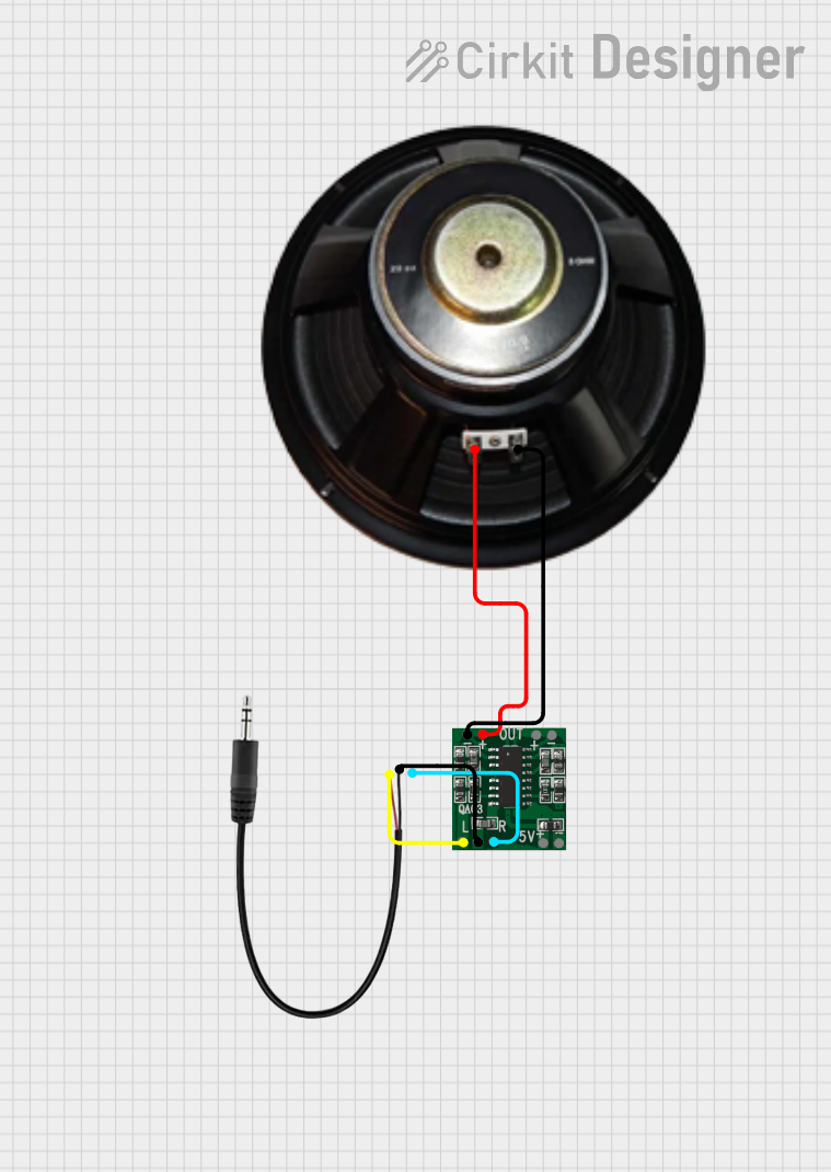
- Input Signal: Feed the audio signal to the non-inverting input (+) pin. The inverting input (-) pin can be connected to ground or used for differential input.
- Output Signal: Connect the output pin to a speaker or headphone through a coupling capacitor to block DC components.
- Gain Adjustment: Use a capacitor between the gain pins (Pins 1 and 8) to set the desired gain. For example, a 10 µF capacitor can provide a gain of 200.
- Bypass Noise: Optionally, connect a capacitor to the bypass pin to reduce noise and improve stability.
Important Considerations and Best Practices
- Speaker Impedance: Ensure the speaker impedance matches the amplifier's output impedance to avoid distortion or damage.
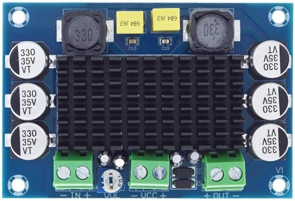
- Heat Dissipation: Use a heat sink if the amplifier generates significant heat during operation.
- Power Supply Filtering: Add decoupling capacitors near the power supply pins to reduce noise and voltage fluctuations.
- Avoid Overloading: Do not exceed the amplifier's maximum output power to prevent damage to the IC or connected components.
Example: Connecting an Audio Amplifier to an Arduino UNO
Below is an example of how to use an LM386 audio amplifier with an Arduino UNO to play a simple tone.
Circuit Connections
- Connect the LM386's Vcc pin to the Arduino's 5V pin and GND to the Arduino's GND.
- Connect the Arduino's PWM output pin (e.g., Pin 9) to the LM386's non-inverting input (+) pin through a 10 µF capacitor.
- Connect a speaker to the LM386's output pin through a 220 µF capacitor.
- Add a 10 µF capacitor between Pins 1 and 8 of the LM386 to set the gain.
Arduino Code
// Simple Arduino code to generate a tone using an LM386 audio amplifier
const int speakerPin = 9; // PWM pin connected to the amplifier's input

void setup() {
  pinMode(speakerPin, OUTPUT); // Set the speaker pin as an output
}

void loop() {
  // Generate a 1 kHz tone for 1 second
  tone(speakerPin, 1000, 1000);
  delay(2000); // Wait for 2 seconds before repeating
}
Troubleshooting and FAQs
Common Issues Users Might Face
No Sound Output:
- Check the power supply connections and ensure the amplifier is receiving the correct voltage.
- Verify that the input signal is present and properly connected.
- Ensure the speaker is functional and correctly connected to the output pin.
Distorted Sound:
- Check if the speaker impedance matches the amplifier's output impedance.
- Reduce the input signal amplitude if it is too high.
- Ensure the gain is not set too high, as this can cause clipping.
Excessive Noise:
- Add a capacitor to the bypass pin to reduce noise.
- Use shielded cables for the input signal to minimize interference.
- Ensure proper grounding to avoid ground loops.
Overheating:
- Check if the amplifier is overloaded or driving a speaker with too low an impedance.
- Use a heat sink to dissipate heat effectively.
Solutions and Tips for Troubleshooting
- Use an oscilloscope to check the input and output signals for proper operation.
- Double-check all connections and ensure components are soldered correctly.
- Refer to the amplifier's datasheet for specific recommendations and limitations.
By following this documentation, users can effectively integrate an audio amplifier into their projects and troubleshoot common issues with ease.