How to Use esp32-dev-38p_pin_detail: Examples, Pinouts, and Specs
Introduction
The ESP32-DEV-38P is a development board manufactured by Seeit, based on the ESP32 microcontroller (part ID: ESP32). This board features a detailed pinout with 38 pins, including GPIO, power, and communication interfaces, making it a versatile choice for IoT, embedded systems, and prototyping applications. The ESP32 is known for its dual-core processor, integrated Wi-Fi, and Bluetooth capabilities, making it ideal for wireless communication and smart device projects.
Explore Projects Built with esp32-dev-38p_pin_detail


Explore Projects Built with esp32-dev-38p_pin_detail
Common Applications
- IoT devices and smart home automation
- Wireless communication systems (Wi-Fi and Bluetooth)
- Sensor interfacing and data logging
- Robotics and motor control
- Prototyping and educational projects
Technical Specifications
The ESP32-DEV-38P board is designed to provide a wide range of functionalities through its 38 pins. Below are the key technical details and pin configurations:
Key Technical Details
- Microcontroller: ESP32 (dual-core, 32-bit LX6 processor)
- Operating Voltage: 3.3V
- Input Voltage (VIN): 5V (via USB or external power supply)
- Wi-Fi: IEEE 802.11 b/g/n
- Bluetooth: v4.2 BR/EDR and BLE
- Flash Memory: 4MB (varies by model)
- GPIO Pins: 34 (multipurpose, configurable)
- Analog Inputs: 18 (ADC1 and ADC2)
- PWM Outputs: 16
- Communication Interfaces: UART, SPI, I2C, I2S
- Current Consumption: ~240mA (Wi-Fi active), ~10µA (deep sleep)
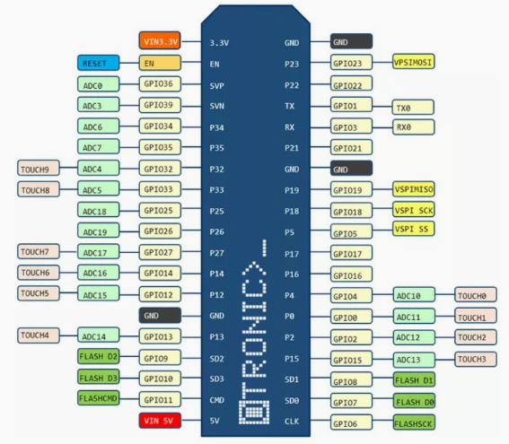
Pin Configuration and Descriptions
The ESP32-DEV-38P features 38 pins, each with specific functions. Below is a detailed pinout table:
| Pin Number | Pin Name | Function |
|---|---|---|
| 1 | GND | Ground |
| 2 | VIN | Input voltage (5V) |
| 3 | 3V3 | 3.3V output |
| 4 | EN | Enable pin (active high, resets the chip when pulled low) |
| 5 | IO0 | GPIO0, boot mode selection, can also be used as a general-purpose pin |
| 6 | IO1 (TX0) | GPIO1, UART0 TX (serial communication) |
| 7 | IO2 | GPIO2, supports PWM, ADC, and other functions |
| 8 | IO3 (RX0) | GPIO3, UART0 RX (serial communication) |
| 9 | IO4 | GPIO4, supports PWM, ADC, and other functions |
| 10 | IO5 | GPIO5, supports PWM, ADC, and other functions |
| 11 | IO12 | GPIO12, supports ADC, touch sensing, and PWM |
| 12 | IO13 | GPIO13, supports ADC, touch sensing, and PWM |
| 13 | IO14 | GPIO14, supports ADC, touch sensing, and PWM |
| 14 | IO15 | GPIO15, supports ADC, touch sensing, and PWM |
| 15 | IO16 | GPIO16, supports ADC and other functions |
| 16 | IO17 | GPIO17, supports ADC and other functions |
| 17 | IO18 | GPIO18, SPI clock (SCK), supports PWM |
| 18 | IO19 | GPIO19, SPI MISO, supports PWM |
| 19 | IO21 | GPIO21, I2C SDA |
| 20 | IO22 | GPIO22, I2C SCL |
| 21 | IO23 | GPIO23, SPI MOSI, supports PWM |
| 22 | IO25 | GPIO25, DAC1, supports PWM |
| 23 | IO26 | GPIO26, DAC2, supports PWM |
| 24 | IO27 | GPIO27, supports ADC, touch sensing, and PWM |
| 25 | IO32 | GPIO32, ADC1 channel, touch sensing |
| 26 | IO33 | GPIO33, ADC1 channel, touch sensing |
| 27 | IO34 | GPIO34, ADC1 channel (input only) |
| 28 | IO35 | GPIO35, ADC1 channel (input only) |
| 29 | IO36 | GPIO36, ADC1 channel (input only) |
| 30 | IO39 | GPIO39, ADC1 channel (input only) |
| 31 | TXD0 | UART0 TX (default serial communication) |
| 32 | RXD0 | UART0 RX (default serial communication) |
| 33 | BOOT | Boot mode selection pin |
| 34 | RST | Reset pin |
Usage Instructions
How to Use the ESP32-DEV-38P in a Circuit
Powering the Board:
- Connect the VIN pin to a 5V power source or use the micro-USB port for power and programming.
- Ensure the GND pin is connected to the ground of your circuit.
Programming the ESP32:
- Use the Arduino IDE or ESP-IDF for programming.
- Select "ESP32 Dev Module" as the board in the Arduino IDE.
- Connect the board to your computer via USB and upload your code.
GPIO Usage:
- Configure GPIO pins as input or output in your code.
- Use pull-up or pull-down resistors as needed for stable input signals.
Communication Interfaces:
- Use UART, SPI, or I2C for interfacing with sensors, displays, or other peripherals.
- Ensure proper pin connections for the selected communication protocol.
Wi-Fi and Bluetooth:
- Use the built-in Wi-Fi and Bluetooth libraries to enable wireless communication.
- Configure the network credentials in your code for Wi-Fi connectivity.
Example Code for Arduino UNO
Below is an example of using the ESP32 to blink an LED connected to GPIO2:
// Define the GPIO pin for the LED
#define LED_PIN 2

void setup() {
  // Initialize the LED pin as an output
  pinMode(LED_PIN, OUTPUT);
}

void loop() {
  // Turn the LED on
  digitalWrite(LED_PIN, HIGH);
  delay(1000); // Wait for 1 second

  // Turn the LED off
  digitalWrite(LED_PIN, LOW);
  delay(1000); // Wait for 1 second
}
Important Considerations
- Avoid exceeding the maximum voltage ratings for GPIO pins (3.3V).
- Use level shifters when interfacing with 5V devices.
- Ensure proper grounding to avoid noise and instability in the circuit.
- Use decoupling capacitors near the power pins for stable operation.
Troubleshooting and FAQs
Common Issues
Board Not Detected by Computer:
- Ensure the USB cable is functional and supports data transfer.
- Install the correct USB-to-serial driver for the ESP32.
Upload Errors in Arduino IDE:
- Check the selected board and COM port in the Arduino IDE.
- Press and hold the BOOT button while uploading the code.
Wi-Fi Connection Fails:
- Verify the SSID and password in your code.
- Ensure the Wi-Fi network is within range.
GPIO Pin Not Working:
- Check if the pin is configured correctly in the code.
- Ensure the pin is not being used for another function (e.g., boot mode).
Tips for Troubleshooting
- Use a multimeter to check voltage levels on power and GPIO pins.
- Test the board with a simple blink sketch to verify basic functionality.
- Refer to the ESP32 datasheet for detailed electrical characteristics and pin functions.
This documentation provides a comprehensive guide to understanding and using the ESP32-DEV-38P development board. For further assistance, consult the official Seeit documentation or community forums.