How to Use esp32-wroom-32e dev board: Examples, Pinouts, and Specs
Introduction
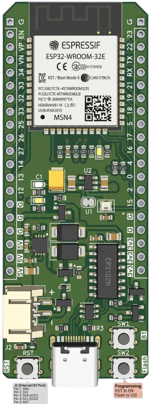
The ESP32-WROOM-32E Dev Board by Pandabyte (Part ID: esp32wroom32e) is a versatile development board built around the ESP32-WROOM-32E module. This module integrates a powerful dual-core Xtensa® 32-bit LX6 microprocessor, Wi-Fi, and Bluetooth capabilities, making it an excellent choice for IoT applications, smart devices, and rapid prototyping.
Explore Projects Built with esp32-wroom-32e dev board


Explore Projects Built with esp32-wroom-32e dev board
Common Applications and Use Cases
- IoT devices and smart home automation
- Wireless sensor networks
- Wearable technology
- Industrial automation
- Prototyping for Wi-Fi and Bluetooth-enabled projects
- Educational and hobbyist projects
Technical Specifications
The ESP32-WROOM-32E Dev Board is designed to provide robust performance and flexibility for a wide range of applications. Below are the key technical details:
General Specifications
| Parameter | Value |
|---|---|
| Microcontroller | ESP32-WROOM-32E (Xtensa® 32-bit LX6 dual-core) |
| Clock Speed | Up to 240 MHz |
| Flash Memory | 4 MB (embedded in module) |
| SRAM | 520 KB |
| Wireless Connectivity | Wi-Fi 802.11 b/g/n, Bluetooth v4.2 BR/EDR/LE |
| Operating Voltage | 3.3V |
| Input Voltage (VIN) | 5V (via USB or VIN pin) |
| GPIO Pins | 34 (multipurpose, including ADC, DAC, PWM) |
| Communication Interfaces | UART, SPI, I2C, I2S, CAN, PWM |
| Power Consumption | Ultra-low power modes available |
| Dimensions | 25.5 mm x 51 mm |
Pin Configuration and Descriptions
The ESP32-WROOM-32E Dev Board features a 38-pin layout. Below is the pin configuration:
| Pin Number | Pin Name | Description |
|---|---|---|
| 1 | EN | Reset pin (active high) |
| 2 | IO0 | GPIO0, used for boot mode selection |
| 3 | IO1 | GPIO1, UART TXD |
| 4 | IO2 | GPIO2, ADC2 channel 2 |
| 5 | IO3 | GPIO3, UART RXD |
| ... | ... | ... (Refer to the full datasheet for all pins) |
| 37 | GND | Ground |
| 38 | 3V3 | 3.3V power output |
Note: Some GPIO pins have specific functions or limitations (e.g., ADC2 pins cannot be used when Wi-Fi is active). Refer to the ESP32-WROOM-32E datasheet for detailed pin functionality.
Usage Instructions
The ESP32-WROOM-32E Dev Board is easy to use and compatible with popular development environments such as Arduino IDE, PlatformIO, and ESP-IDF. Below are the steps to get started:
Setting Up the Development Environment
- Install Drivers: Ensure the USB-to-serial driver for the board is installed on your computer.
- Download Arduino IDE: Install the latest version of the Arduino IDE from arduino.cc.
- Add ESP32 Board Support:
- Open Arduino IDE and go to
File > Preferences. - In the "Additional Board Manager URLs" field, add the following URL:
https://dl.espressif.com/dl/package_esp32_index.json - Go to
Tools > Board > Boards Manager, search for "ESP32", and install the package.
- Open Arduino IDE and go to
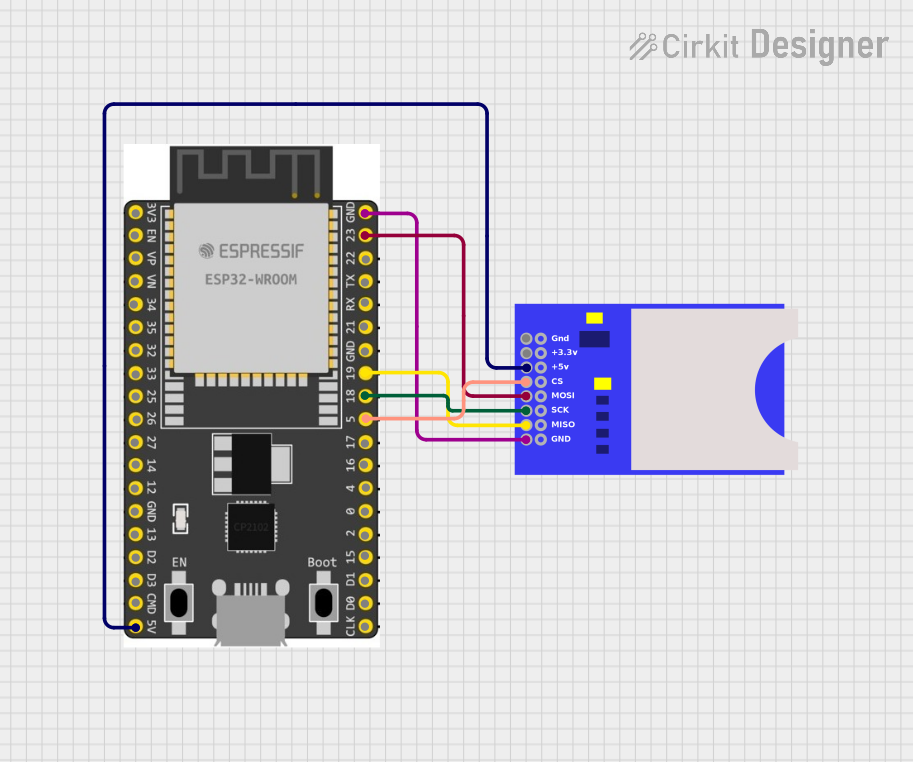
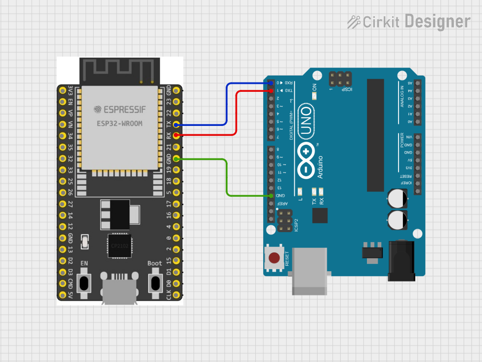
Basic Circuit Connection
- Connect the ESP32-WROOM-32E Dev Board to your computer using a micro-USB cable.
- Ensure the board is powered via USB or an external 5V source through the VIN pin.
- Use the onboard GPIO pins to connect sensors, actuators, or other peripherals.
Example Code: Blink an LED
The following example demonstrates how to blink an LED connected to GPIO2:
// Blink an LED connected to GPIO2 on the ESP32-WROOM-32E Dev Board

#define LED_PIN 2  // Define the GPIO pin for the LED

void setup() {
  pinMode(LED_PIN, OUTPUT);  // Set GPIO2 as an output pin
}

void loop() {
  digitalWrite(LED_PIN, HIGH);  // Turn the LED on
  delay(1000);                 // Wait for 1 second
  digitalWrite(LED_PIN, LOW);   // Turn the LED off
  delay(1000);                 // Wait for 1 second
}
Important Considerations and Best Practices
- Power Supply: Ensure the board is powered with a stable 5V source via USB or VIN.
- GPIO Voltage Levels: The GPIO pins operate at 3.3V logic levels. Avoid applying 5V directly to GPIO pins.
- Boot Mode: To enter bootloader mode, hold the
BOOTbutton while pressing theENbutton. - Wi-Fi and Bluetooth: Using these features simultaneously may increase power consumption.
Troubleshooting and FAQs
Common Issues
Board Not Detected by Computer:
- Ensure the USB cable is functional and supports data transfer.
- Install the correct USB-to-serial driver for your operating system.
Upload Fails in Arduino IDE:
- Check the selected board and port under
Tools > BoardandTools > Port. - Press and hold the
BOOTbutton while uploading the code.
- Check the selected board and port under
Wi-Fi Connection Issues:
- Verify the SSID and password in your code.
- Ensure the Wi-Fi network is within range and not using unsupported security protocols.
GPIO Pin Not Working:
- Check if the pin is reserved for specific functions (e.g., GPIO0 for boot mode).
- Ensure no conflicting peripherals are using the same pin.
FAQs
Q: Can I power the board using a battery?
A: Yes, you can power the board using a 3.7V LiPo battery connected to the 3V3 pin or a 5V source connected to the VIN pin.
Q: Is the ESP32-WROOM-32E compatible with Arduino libraries?
A: Yes, the ESP32-WROOM-32E is compatible with most Arduino libraries, but some may require modifications for ESP32-specific features.
Q: How do I reset the board?
A: Press the EN button to reset the board.
Q: Can I use the ADC pins while Wi-Fi is active?
A: ADC2 pins cannot be used when Wi-Fi is active. Use ADC1 pins for analog input in such cases.
By following this documentation, you can effectively utilize the ESP32-WROOM-32E Dev Board for your projects. For advanced features and configurations, refer to the official ESP32-WROOM-32E datasheet and Pandabyte's resources.