How to Use Adafruit Metro ESP32-S2: Examples, Pinouts, and Specs
Introduction
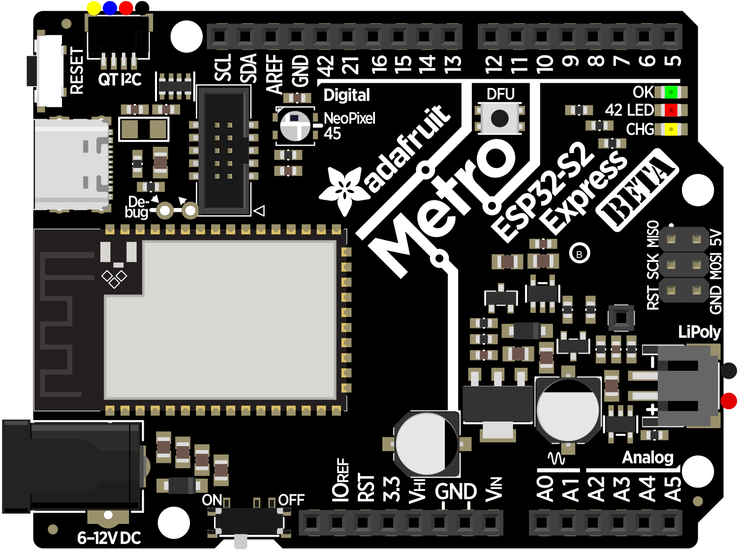
The Adafruit Metro ESP32-S2 is a versatile and powerful development board that harnesses the capabilities of the ESP32-S2 chip. This board is designed for a wide range of applications, from Internet of Things (IoT) projects to complex wireless communication systems. With built-in Wi-Fi, USB connectivity, and an extensive array of General Purpose Input/Output (GPIO) pins, the Metro ESP32-S2 is a go-to choice for hobbyists and professionals alike.
Explore Projects Built with Adafruit Metro ESP32-S2


Explore Projects Built with Adafruit Metro ESP32-S2
Common Applications and Use Cases
- IoT devices
- Wireless sensor networks
- Home automation systems
- DIY electronics projects
- Prototyping for embedded systems
Technical Specifications
Key Technical Details
- Microcontroller: ESP32-S2
- Operating Voltage: 3.3V
- Input Voltage (recommended): 5V via USB or battery
- Digital I/O Pins: 21, all of which can do PWM
- Analog Input Pins: 16
- Flash Memory: 4 MB
- SRAM: 320 KB
- Clock Speed: 240 MHz
- Wi-Fi: 802.11 b/g/n
- USB: USB-C for programming and power
Pin Configuration and Descriptions
| Pin Number | Function | Description |
|---|---|---|
| 1 | 3V3 | 3.3V power supply pin |
| 2 | GND | Ground |
| 3-5 | GPIO 1, 2, 3 | General Purpose Input/Output |
| 6 | TX0 | UART transmit |
| 7 | RX0 | UART receive |
| 8-10 | GPIO 4, 5, 6 | General Purpose Input/Output |
| 11 | SDA | I2C data line |
| 12 | SCL | I2C clock line |
| 13-17 | GPIO 7-11 | General Purpose Input/Output |
| 18 | A0 | Analog input channel 0 |
| 19-34 | A1-A16 | Analog input channels 1-16 |
| 35 | VIN | Input voltage for battery or unregulated power |
Usage Instructions
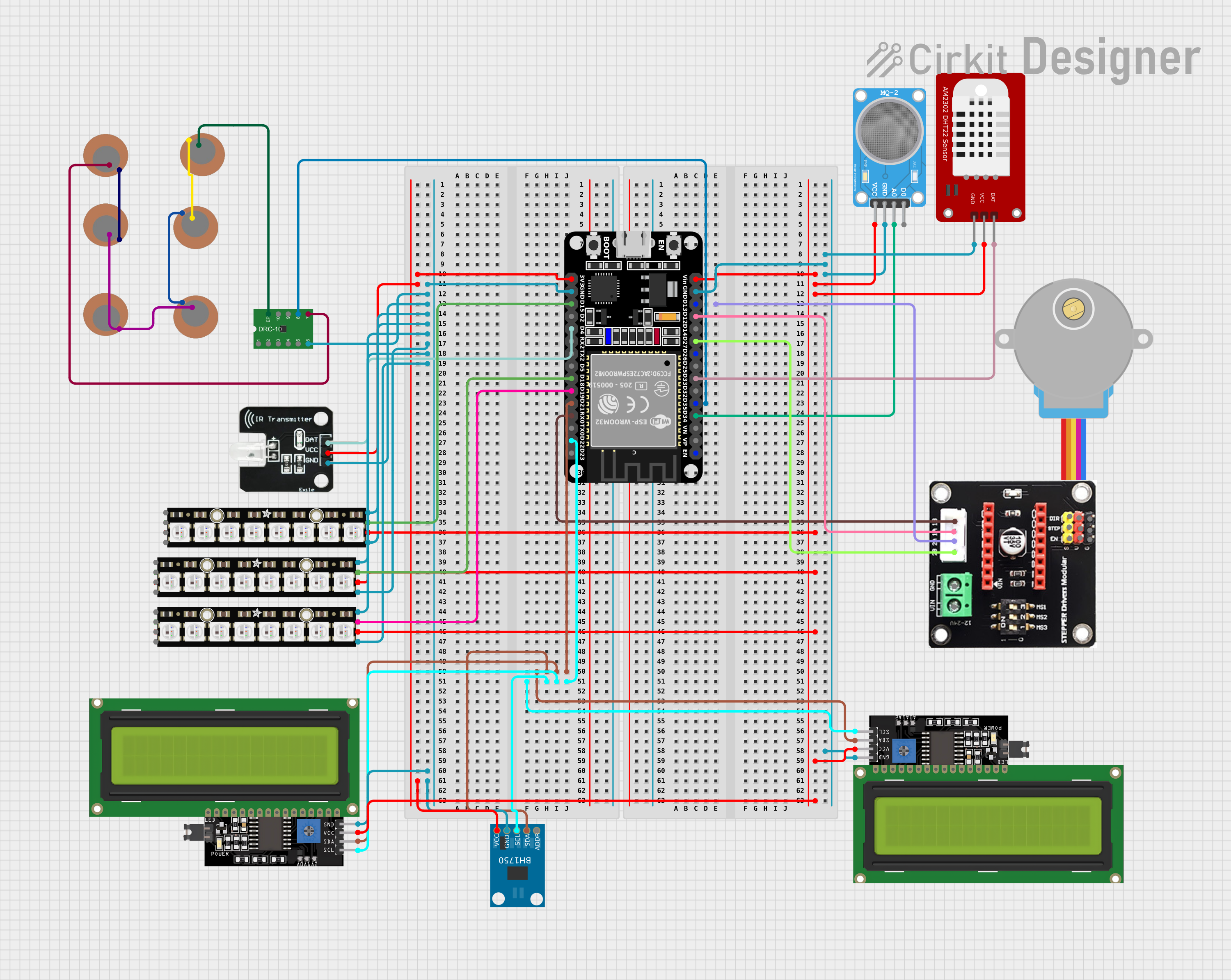
How to Use the Component in a Circuit
- Powering the Board: Connect the USB-C cable to the board and a power source, or attach a battery to the VIN pin.
- Connecting I/O: Utilize the GPIO pins for digital input/output or PWM. Analog pins can be used for reading analog sensors.
- Programming: Use the USB-C connection to program the board with the Arduino IDE or other compatible development environments.
Important Considerations and Best Practices
- Ensure that the input voltage does not exceed the recommended 5V to prevent damage.
- When using Wi-Fi, take into account power consumption and possible interference with other wireless devices.
- Use proper decoupling capacitors close to the board's power pins to minimize noise.
- Avoid drawing more than 12 mA from any GPIO pin.
- For high-frequency PWM, consult the ESP32-S2 datasheet for optimal configurations.
Troubleshooting and FAQs
Common Issues
- Board not recognized by computer: Check the USB cable and port, try a different cable or port, and ensure drivers are installed.
- Wi-Fi connectivity issues: Verify Wi-Fi credentials, check signal strength, and ensure the antenna is not obstructed.
- Unexpected resets or crashes: This can be due to power supply issues. Make sure the power source is stable and within the specified voltage range.
Solutions and Tips for Troubleshooting
- Use Serial Monitor: Open the Serial Monitor in the Arduino IDE to check for error messages or debug output.
- Firmware Update: Ensure the board's firmware is up to date with the latest version.
- Community Forums: Adafruit has a supportive community forum where you can seek help for more complex issues.
Example Code for Arduino UNO
Below is a simple example of how to blink an LED connected to a GPIO pin on the Adafruit Metro ESP32-S2 using the Arduino IDE.
// Define the LED pin
const int LED_PIN = 13; // Use the onboard LED pin

// Setup function runs once at the start
void setup() {
  // Initialize the LED pin as an output
  pinMode(LED_PIN, OUTPUT);
}

// Loop function runs over and over again forever
void loop() {
  digitalWrite(LED_PIN, HIGH);   // Turn the LED on
  delay(1000);                   // Wait for a second
  digitalWrite(LED_PIN, LOW);    // Turn the LED off
  delay(1000);                   // Wait for a second
}
Remember to select the correct board and port in the Arduino IDE before uploading the code to the Adafruit Metro ESP32-S2.
For more complex applications involving Wi-Fi and IoT, refer to the ESP32-S2 specific libraries and examples provided by Adafruit and the ESP32 community.