How to Use ADS1118 - ADC: Examples, Pinouts, and Specs
Introduction
The ADS1118 is a high-precision, 16-bit analog-to-digital converter (ADC) manufactured by Texas Instruments. It features an integrated programmable gain amplifier (PGA) and operates over an I2C-compatible interface. This versatile component is designed for precision measurement applications, offering low power consumption and support for multiple input channels. Its compact VSSOP package makes it ideal for space-constrained designs.
Explore Projects Built with ADS1118 - ADC
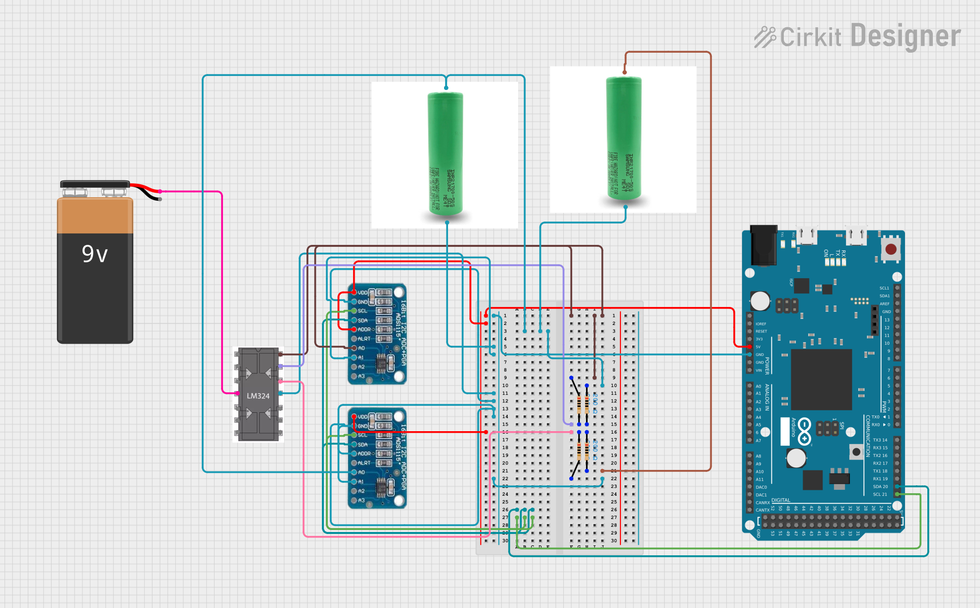
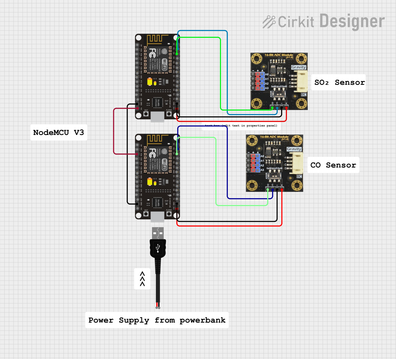

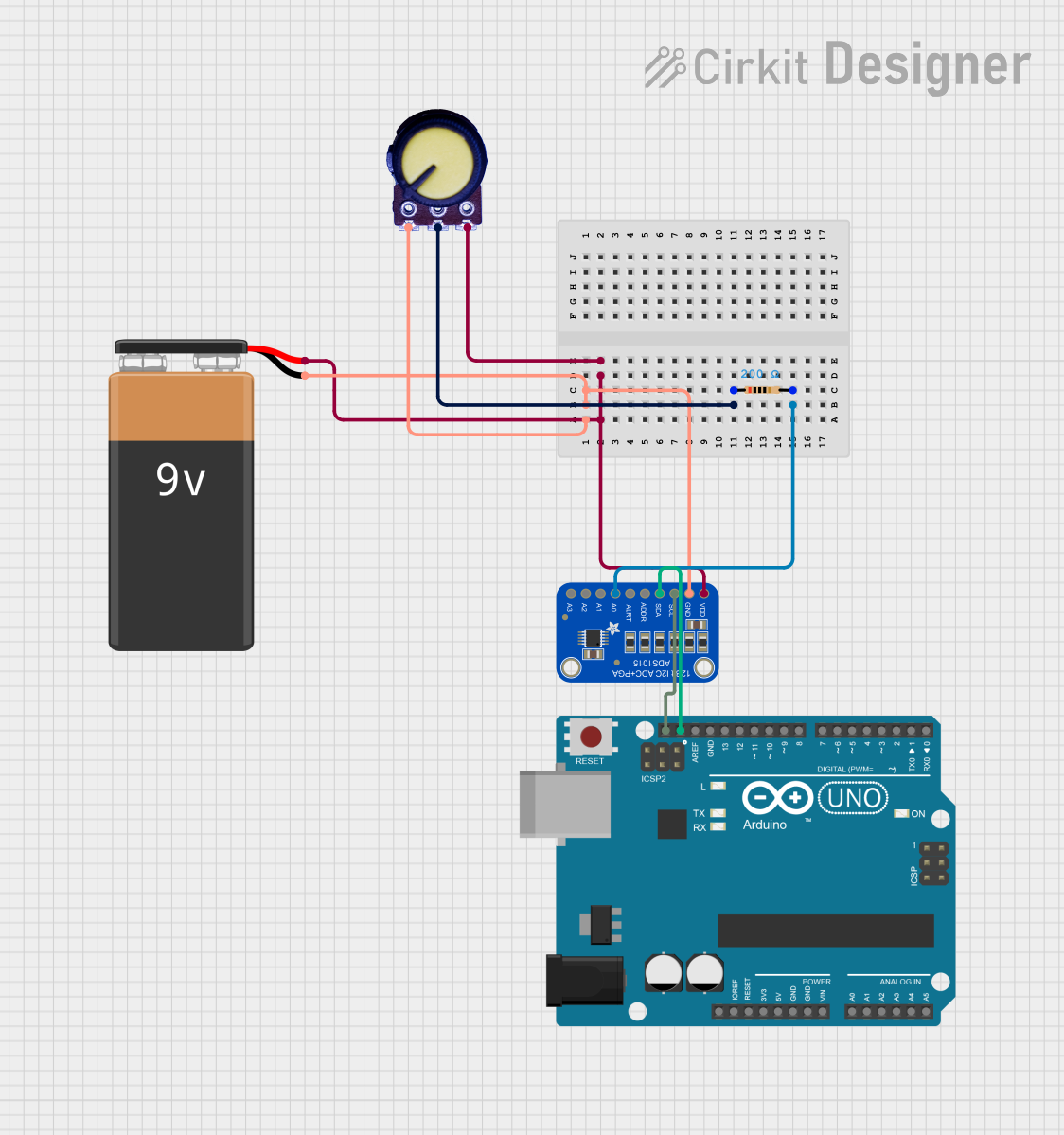
Explore Projects Built with ADS1118 - ADC
Common Applications
- Temperature sensing (e.g., thermocouples, RTDs)
- Battery monitoring
- Portable medical devices
- Industrial process control
- Data acquisition systems
Technical Specifications
Key Features
- Resolution: 16 bits
- Input Channels: 4 single-ended or 2 differential
- Input Voltage Range: ±0.256 V to ±6.144 V (configurable via PGA)
- Supply Voltage: 2.0 V to 5.5 V
- Interface: I2C-compatible
- Conversion Rate: Up to 860 samples per second (SPS)
- Operating Temperature Range: -40°C to +125°C
- Power Consumption:
- Active Mode: 150 µA (typical)
- Power-Down Mode: 0.5 µA (typical)
- Package: VSSOP-10
Pin Configuration and Descriptions
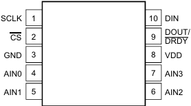
The ADS1118 is available in a 10-pin VSSOP package. Below is the pinout and description:
| Pin | Name | Type | Description |
|---|---|---|---|
| 1 | VDD | Power | Positive supply voltage (2.0 V to 5.5 V). |
| 2 | AIN0 | Analog Input | Analog input channel 0. |
| 3 | AIN1 | Analog Input | Analog input channel 1. |
| 4 | AIN2 | Analog Input | Analog input channel 2. |
| 5 | AIN3 | Analog Input | Analog input channel 3. |
| 6 | GND | Ground | Ground reference for the device. |
| 7 | SCL | Digital Input | I2C clock line. |
| 8 | SDA | Digital I/O | I2C data line. |
| 9 | DRDY | Digital Output | Data ready signal (active low). |
| 10 | NC | - | No connection. |
Usage Instructions
How to Use the ADS1118 in a Circuit
- Power Supply: Connect the VDD pin to a stable power source (2.0 V to 5.5 V) and the GND pin to ground.
- Analog Inputs: Connect the analog signals to the AINx pins. Configure the input mode (single-ended or differential) in the device's configuration register.
- I2C Interface: Connect the SCL and SDA pins to the corresponding I2C lines of your microcontroller. Use pull-up resistors (typically 4.7 kΩ) on both lines.
- Data Ready Signal: Optionally, use the DRDY pin to monitor when a conversion is complete.
- Configuration: Program the ADS1118 via the I2C interface to set the desired gain, data rate, and input channel.
Important Considerations
- Input Voltage Range: Ensure the input voltage does not exceed the configured PGA range or the device's absolute maximum ratings.
- Bypass Capacitor: Place a 0.1 µF ceramic capacitor close to the VDD pin for power supply decoupling.
- Thermocouple Applications: The ADS1118 includes an internal temperature sensor for cold-junction compensation, making it suitable for thermocouple measurements.
- I2C Address: The default 7-bit I2C address of the ADS1118 is
0x48.
Example Code for Arduino UNO
Below is an example of how to interface the ADS1118 with an Arduino UNO to read a single-ended input:
#include <Wire.h>

// ADS1118 I2C address
#define ADS1118_ADDRESS 0x48

// Configuration register settings
#define CONFIG_REGISTER 0x8583  // Single-ended AIN0, ±4.096V, 128 SPS

void setup() {
  Wire.begin();  // Initialize I2C communication
  Serial.begin(9600);  // Initialize serial communication for debugging

  // Configure the ADS1118
  Wire.beginTransmission(ADS1118_ADDRESS);
  Wire.write(CONFIG_REGISTER >> 8);  // Send MSB of configuration register
  Wire.write(CONFIG_REGISTER & 0xFF);  // Send LSB of configuration register
  Wire.endTransmission();
}

void loop() {
  int16_t adcValue;

  // Request conversion result
  Wire.requestFrom(ADS1118_ADDRESS, 2);
  if (Wire.available() == 2) {
    adcValue = (Wire.read() << 8) | Wire.read();  // Combine MSB and LSB
  }

  // Convert ADC value to voltage (assuming ±4.096V range)
  float voltage = (adcValue * 4.096) / 32768.0;

  // Print the voltage to the serial monitor
  Serial.print("Voltage: ");
  Serial.print(voltage, 4);  // Print with 4 decimal places
  Serial.println(" V");

  delay(500);  // Wait 500 ms before the next reading
}
Notes on the Code
- The configuration register value (
0x8583) sets the ADS1118 to read from AIN0 in single-ended mode, with a ±4.096 V range and a data rate of 128 SPS. - Modify the configuration register value to change the input channel, gain, or data rate as needed.
Troubleshooting and FAQs
Common Issues
No I2C Communication:
- Ensure the pull-up resistors (4.7 kΩ) are connected to the SCL and SDA lines.
- Verify the I2C address (
0x48) matches the ADS1118's default address. - Check the wiring between the microcontroller and the ADS1118.
Incorrect Voltage Readings:
- Confirm the input voltage is within the configured PGA range.
- Verify the configuration register settings for the desired input mode and gain.
- Ensure proper grounding and shielding to minimize noise.
Device Not Responding:
- Check the power supply voltage (VDD) and ensure it is within the specified range.
- Verify the I2C clock frequency does not exceed 400 kHz.
FAQs
Q: Can the ADS1118 measure negative voltages?
A: Yes, in differential mode, the ADS1118 can measure negative voltages relative to the reference input.
Q: What is the maximum sampling rate of the ADS1118?
A: The maximum sampling rate is 860 samples per second (SPS).
Q: How do I use the internal temperature sensor?
A: Configure the ADS1118 to read from the temperature sensor by setting the appropriate bits in the configuration register. The temperature data is returned in the conversion result.
Q: Can I use the ADS1118 with a 3.3 V microcontroller?
A: Yes, the ADS1118 operates with supply voltages as low as 2.0 V, making it compatible with 3.3 V systems.
Q: Is the ADS1118 suitable for battery-powered applications?
A: Yes, the ADS1118's low power consumption (150 µA in active mode) makes it ideal for battery-operated devices.