Cirkit Designer Logo
Cirkit Designer
Your all-in-one circuit design IDE
Home / 
Component Documentation

How to Use Pimorini PGA2350 Raspberry pi 2 based microcontroller: Examples, Pinouts, and Specs

Image of Pimorini PGA2350 Raspberry pi 2 based microcontroller
Cirkit Designer LogoDesign with Pimorini PGA2350 Raspberry pi 2 based microcontroller in Cirkit Designer

Introduction

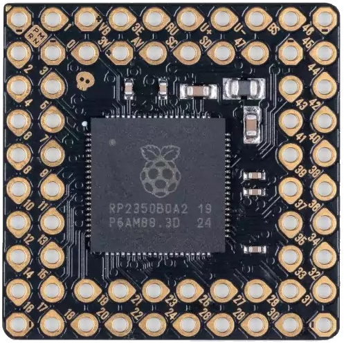
The Pimorini PGA2350 is a versatile microcontroller board designed specifically for use with the Raspberry Pi 2. It features a wide range of GPIO pins and interfaces, making it an excellent choice for hobbyists, students, and professionals working on electronic projects. The PGA2350 is ideal for applications such as robotics, IoT devices, home automation, and sensor integration. Its compatibility with the Raspberry Pi 2 ensures seamless integration and ease of use.

Explore Projects Built with Pimorini PGA2350 Raspberry pi 2 based microcontroller

Use Cirkit Designer to design, explore, and prototype these projects online. Some projects support real-time simulation. Click "Open Project" to start designing instantly!
Raspberry Pi Pico and OV7670 Camera-Based Robotic System with TFT Display
Image of REF Speed Bot V3 CKT: A project utilizing Pimorini PGA2350 Raspberry pi 2 based microcontroller in a practical application
This circuit features two Raspberry Pi Pico microcontrollers interfacing with various peripherals including an OV7670 camera module, a TFT display, and an OLED display. It also includes a multiplexer and a motor driver to control two planetary gearbox motors, powered by a battery and regulated through buck converters. The setup is designed for image capture, display, and motor control applications.
Cirkit Designer LogoOpen Project in Cirkit Designer
Raspberry Pi Pico-Based Navigation System with Bluetooth and GPS
Image of sat_dish: pwm application: A project utilizing Pimorini PGA2350 Raspberry pi 2 based microcontroller in a practical application
This circuit features a Raspberry Pi Pico microcontroller interfaced with multiple peripherals for navigation and control. It includes an HC-05 Bluetooth module for wireless communication, an HMC5883L compass for magnetic heading detection, a GPS NEO 6M module for location tracking, and an SG90 servomotor for actuation. The Pico manages data exchange with the GPS and compass via serial connections, controls the servomotor, and communicates wirelessly through the HC-05 module.
Cirkit Designer LogoOpen Project in Cirkit Designer
Raspberry Pi Pico W-Based Smart Home Automation System with Motion Detection and Environmental Monitoring
Image of Smart Home Automation 1: A project utilizing Pimorini PGA2350 Raspberry pi 2 based microcontroller in a practical application
This circuit features a Raspberry Pi Pico W microcontroller connected to various sensors and actuators, including a DHT11 temperature and humidity sensor, an RCWL-0516 microwave radar motion sensor, a photocell (LDR) with a resistor for light detection, and a two-channel relay controlling a bulb and a fan. The microcontroller runs code to monitor environmental conditions and motion, displaying information on an LCD and allowing remote control via MQTT messages over Wi-Fi. It supports both automatic sensor-based operation and remote app control, with pushbuttons to switch between modes.
Cirkit Designer LogoOpen Project in Cirkit Designer
Raspberry Pi Pico Controlled Robot with Ultrasonic Sensing and Light Detection
Image of MED412: A project utilizing Pimorini PGA2350 Raspberry pi 2 based microcontroller in a practical application
This circuit features a Raspberry Pi Pico microcontroller as the central processing unit, interfacing with a variety of components. It controls a servo motor, reads from a photocell (LDR) with a resistor forming a voltage divider, and communicates with an HC-SR04 ultrasonic sensor for distance measurement. The circuit also includes an L298N motor driver to operate two DC gearmotors, with power regulation provided by a buck converter connected to a DC power source.
Cirkit Designer LogoOpen Project in Cirkit Designer

Explore Projects Built with Pimorini PGA2350 Raspberry pi 2 based microcontroller

Use Cirkit Designer to design, explore, and prototype these projects online. Some projects support real-time simulation. Click "Open Project" to start designing instantly!
Image of REF Speed Bot V3 CKT: A project utilizing Pimorini PGA2350 Raspberry pi 2 based microcontroller in a practical application
Raspberry Pi Pico and OV7670 Camera-Based Robotic System with TFT Display
This circuit features two Raspberry Pi Pico microcontrollers interfacing with various peripherals including an OV7670 camera module, a TFT display, and an OLED display. It also includes a multiplexer and a motor driver to control two planetary gearbox motors, powered by a battery and regulated through buck converters. The setup is designed for image capture, display, and motor control applications.
Cirkit Designer LogoOpen Project in Cirkit Designer
Image of sat_dish: pwm application: A project utilizing Pimorini PGA2350 Raspberry pi 2 based microcontroller in a practical application
Raspberry Pi Pico-Based Navigation System with Bluetooth and GPS
This circuit features a Raspberry Pi Pico microcontroller interfaced with multiple peripherals for navigation and control. It includes an HC-05 Bluetooth module for wireless communication, an HMC5883L compass for magnetic heading detection, a GPS NEO 6M module for location tracking, and an SG90 servomotor for actuation. The Pico manages data exchange with the GPS and compass via serial connections, controls the servomotor, and communicates wirelessly through the HC-05 module.
Cirkit Designer LogoOpen Project in Cirkit Designer
Image of Smart Home Automation 1: A project utilizing Pimorini PGA2350 Raspberry pi 2 based microcontroller in a practical application
Raspberry Pi Pico W-Based Smart Home Automation System with Motion Detection and Environmental Monitoring
This circuit features a Raspberry Pi Pico W microcontroller connected to various sensors and actuators, including a DHT11 temperature and humidity sensor, an RCWL-0516 microwave radar motion sensor, a photocell (LDR) with a resistor for light detection, and a two-channel relay controlling a bulb and a fan. The microcontroller runs code to monitor environmental conditions and motion, displaying information on an LCD and allowing remote control via MQTT messages over Wi-Fi. It supports both automatic sensor-based operation and remote app control, with pushbuttons to switch between modes.
Cirkit Designer LogoOpen Project in Cirkit Designer
Image of MED412: A project utilizing Pimorini PGA2350 Raspberry pi 2 based microcontroller in a practical application
Raspberry Pi Pico Controlled Robot with Ultrasonic Sensing and Light Detection
This circuit features a Raspberry Pi Pico microcontroller as the central processing unit, interfacing with a variety of components. It controls a servo motor, reads from a photocell (LDR) with a resistor forming a voltage divider, and communicates with an HC-SR04 ultrasonic sensor for distance measurement. The circuit also includes an L298N motor driver to operate two DC gearmotors, with power regulation provided by a buck converter connected to a DC power source.
Cirkit Designer LogoOpen Project in Cirkit Designer

Technical Specifications

The following table outlines the key technical specifications of the Pimorini PGA2350:

Specification Details
Manufacturer Pimorini
Part ID PGA2350
Compatible Platform Raspberry Pi 2
Operating Voltage 3.3V (logic level)
Input Voltage Range 5V (via Raspberry Pi 2 power supply)
GPIO Pins 40 pins (fully compatible with Raspberry Pi 2 GPIO header)
Communication Interfaces I2C, SPI, UART
PWM Channels 4
ADC Channels 2 (10-bit resolution)
Maximum Current Output 16mA per GPIO pin
Dimensions 85mm x 56mm
Operating Temperature -20°C to 70°C

Pin Configuration and Descriptions

The Pimorini PGA2350 uses a 40-pin GPIO header, which is fully compatible with the Raspberry Pi 2. Below is the pinout description:

Pin Number Pin Name Function Description
1 3.3V Power 3.3V power supply
2 5V Power 5V power supply
3 GPIO2 (SDA) I2C Data I2C data line
4 5V Power 5V power supply
5 GPIO3 (SCL) I2C Clock I2C clock line
6 GND Ground Ground connection
7 GPIO4 General Purpose I/O GPIO pin
8 GPIO14 (TXD) UART Transmit UART transmit line
9 GND Ground Ground connection
10 GPIO15 (RXD) UART Receive UART receive line
... ... ... ...
39 GND Ground Ground connection
40 GPIO21 General Purpose I/O GPIO pin

For the full pinout, refer to the Pimorini PGA2350 datasheet.

Usage Instructions

How to Use the Component in a Circuit

  1. Powering the Board: The PGA2350 is powered through the Raspberry Pi 2's 5V power supply. Ensure that the Raspberry Pi 2 is properly powered before connecting the PGA2350.
  2. Connecting Peripherals: Use the GPIO pins to connect sensors, actuators, or other peripherals. Ensure that the voltage levels of connected devices are compatible with the 3.3V logic level of the PGA2350.
  3. Programming: The PGA2350 can be programmed using Python or other supported languages on the Raspberry Pi 2. Libraries such as RPi.GPIO or gpiozero can be used for GPIO control.

Important Considerations and Best Practices

  • Voltage Levels: Avoid connecting devices that operate at 5V logic levels directly to the GPIO pins, as this may damage the PGA2350.
  • Current Limits: Do not exceed the maximum current output of 16mA per GPIO pin to prevent damage.
  • Static Protection: Handle the board with care to avoid static discharge, which can damage the microcontroller.
  • Pin Mapping: Double-check the pin mapping to ensure correct connections.

Example Code for GPIO Control

Below is an example of how to blink an LED connected to GPIO4 using Python on the Raspberry Pi 2:

import RPi.GPIO as GPIO  # Import the GPIO library
import time              # Import the time library for delays

Pin configuration

LED_PIN = 4 # GPIO4 is used for the LED

GPIO setup

GPIO.setmode(GPIO.BCM) # Use Broadcom pin numbering GPIO.setup(LED_PIN, GPIO.OUT) # Set GPIO4 as an output pin

try: while True: GPIO.output(LED_PIN, GPIO.HIGH) # Turn the LED on time.sleep(1) # Wait for 1 second GPIO.output(LED_PIN, GPIO.LOW) # Turn the LED off time.sleep(1) # Wait for 1 second except KeyboardInterrupt: # Clean up GPIO settings on exit GPIO.cleanup()


Troubleshooting and FAQs

Common Issues Users Might Face

  1. No Response from GPIO Pins:

    • Cause: Incorrect pin configuration or wiring.
    • Solution: Double-check the pin mapping and ensure proper connections.
  2. Overheating:

    • Cause: Exceeding the current limit of GPIO pins.
    • Solution: Ensure that the connected devices do not draw more than 16mA per pin.
  3. I2C or SPI Communication Fails:

    • Cause: Incorrect configuration or missing pull-up resistors.
    • Solution: Verify the I2C/SPI settings and ensure pull-up resistors are in place for I2C lines.
  4. Board Not Detected by Raspberry Pi:

    • Cause: Improper connection or power supply issues.
    • Solution: Ensure the PGA2350 is securely connected to the Raspberry Pi 2 and that the power supply is adequate.

Solutions and Tips for Troubleshooting

  • Use a multimeter to check voltage levels and continuity of connections.
  • Refer to the Raspberry Pi 2 GPIO documentation for additional guidance on pin usage.
  • Update the Raspberry Pi's firmware and software to ensure compatibility with the PGA2350.

By following this documentation, users can effectively integrate and utilize the Pimorini PGA2350 in their electronic projects.