How to Use Pimorini PGA2350: Examples, Pinouts, and Specs
Introduction
The Pimorini PGA2350 is a high-performance programmable gain amplifier (PGA) designed specifically for audio applications. It provides precise and adjustable gain settings, enabling users to amplify audio signals with minimal noise and distortion. This makes it an ideal choice for high-fidelity audio systems, mixers, and other audio processing equipment.
Explore Projects Built with Pimorini PGA2350


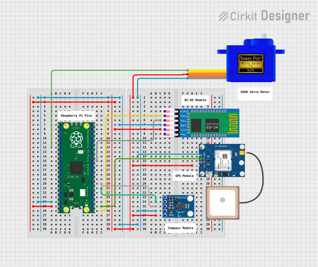
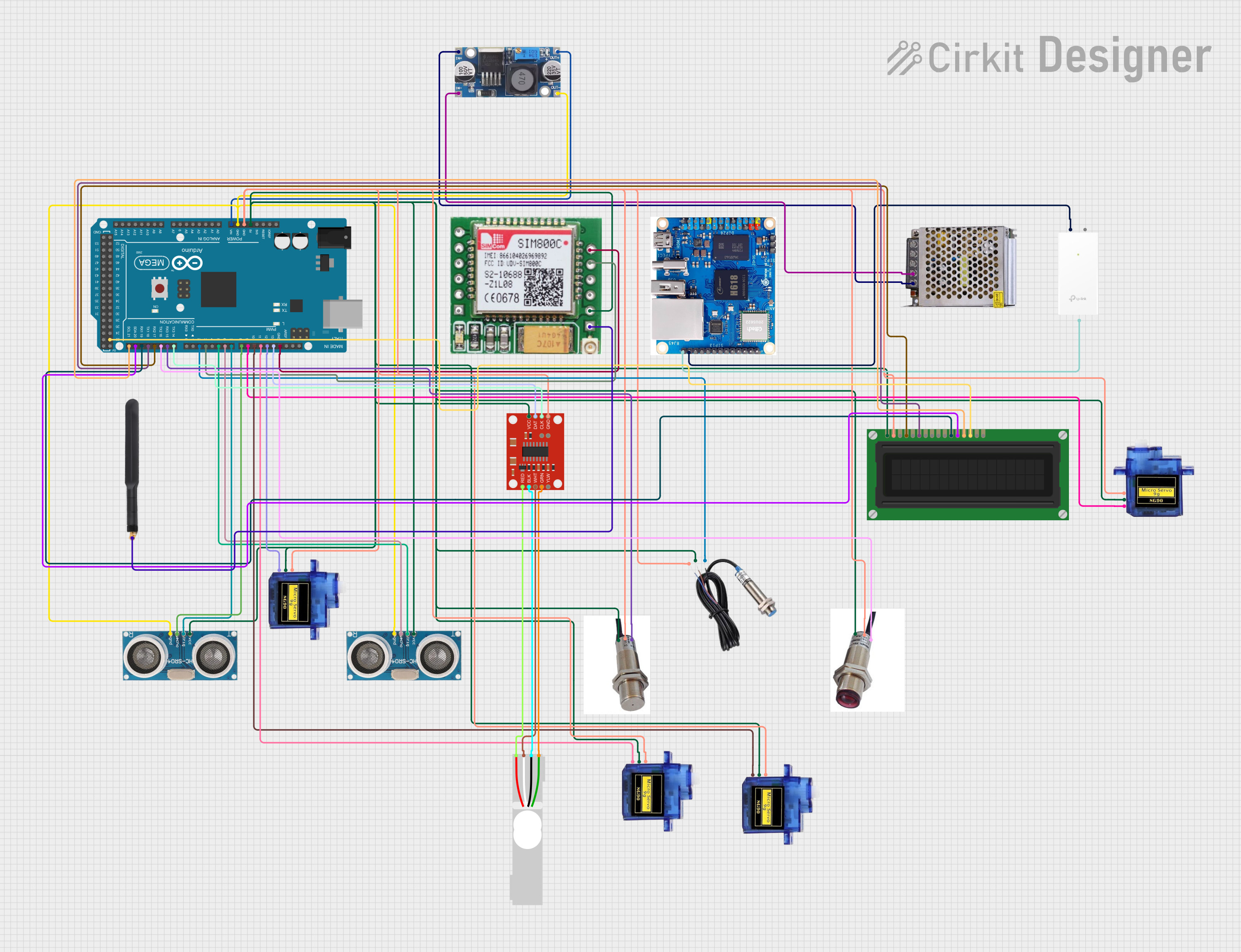
Explore Projects Built with Pimorini PGA2350
Common Applications and Use Cases
- High-fidelity audio systems
- Audio mixers and preamplifiers
- Signal conditioning in audio processing
- Home theater systems
- Professional audio equipment
Technical Specifications
The Pimorini PGA2350 is engineered to deliver exceptional audio performance. Below are its key technical specifications:
| Parameter | Value |
|---|---|
| Supply Voltage (Vcc) | 4.5V to 5.5V |
| Gain Range | -95.5 dB to +31.5 dB (0.5 dB steps) |
| Total Harmonic Distortion | < 0.0004% |
| Signal-to-Noise Ratio | > 120 dB |
| Input Impedance | 10 kΩ |
| Output Impedance | 100 Ω |
| Control Interface | SPI |
| Operating Temperature | -40°C to +85°C |
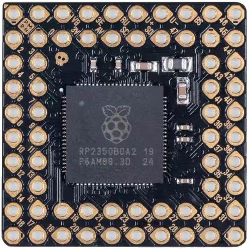
Pin Configuration and Descriptions
The PGA2350 comes in a 16-pin package. Below is the pinout and description:
| Pin Number | Pin Name | Description |
|---|---|---|
| 1 | VCC | Positive power supply (4.5V to 5.5V) |
| 2 | GND | Ground |
| 3 | INL+ | Left channel positive input |
| 4 | INL- | Left channel negative input |
| 5 | INR+ | Right channel positive input |
| 6 | INR- | Right channel negative input |
| 7 | OUTL | Left channel output |
| 8 | OUTR | Right channel output |
| 9 | SCLK | SPI clock input |
| 10 | SDI | SPI data input |
| 11 | CS | Chip select (active low) |
| 12 | MUTE | Mute control (active high) |
| 13 | NC | No connection |
| 14 | NC | No connection |
| 15 | NC | No connection |
| 16 | NC | No connection |
Usage Instructions
The Pimorini PGA2350 is straightforward to integrate into audio circuits. Below are the steps and best practices for using the component:
How to Use the Component in a Circuit
- Power Supply: Connect the VCC pin to a stable 5V power supply and the GND pin to ground.
- Audio Inputs: Connect the audio signal to the INL+/- and INR+/- pins for the left and right channels, respectively.
- Audio Outputs: Connect the OUTL and OUTR pins to the desired output stage (e.g., speakers or further amplification stages).
- SPI Control: Use the SCLK, SDI, and CS pins to configure the gain settings via an SPI-compatible microcontroller.
- Mute Function: Use the MUTE pin to enable or disable the mute function. Pull the pin high to mute the output.
Important Considerations and Best Practices
- Decoupling Capacitors: Place decoupling capacitors (e.g., 0.1 µF and 10 µF) close to the VCC pin to reduce power supply noise.
- Input Coupling: Use coupling capacitors on the input pins to block DC offset from the audio source.
- Output Load: Ensure the output load impedance is within the recommended range to avoid distortion.
- SPI Configuration: Configure the SPI interface with the correct clock polarity and phase settings (CPOL = 0, CPHA = 0).
Example Code for Arduino UNO
Below is an example of how to control the PGA2350 using an Arduino UNO via SPI:
#include <SPI.h>

// Define SPI pins for the PGA2350
const int CS_PIN = 10; // Chip select pin

void setup() {
  // Initialize SPI communication
  SPI.begin();
  pinMode(CS_PIN, OUTPUT);
  digitalWrite(CS_PIN, HIGH); // Set CS pin high (inactive)

  // Configure PGA2350 gain
  setGain(0x20); // Example: Set gain to 0 dB
}

void loop() {
  // Main loop can include additional functionality
}

// Function to set gain on the PGA2350
void setGain(byte gainValue) {
  digitalWrite(CS_PIN, LOW); // Activate chip select
  SPI.transfer(gainValue);   // Send gain value via SPI
  digitalWrite(CS_PIN, HIGH); // Deactivate chip select
}
Troubleshooting and FAQs
Common Issues and Solutions
No Output Signal
- Cause: Incorrect power supply or loose connections.
- Solution: Verify that the VCC and GND pins are properly connected and the supply voltage is within the specified range.
Distorted Audio Output
- Cause: Input or output impedance mismatch.
- Solution: Ensure the input and output impedances match the recommended values. Use coupling capacitors if necessary.
SPI Communication Failure
- Cause: Incorrect SPI configuration or wiring.
- Solution: Double-check the SPI clock polarity and phase settings. Ensure the SCLK, SDI, and CS pins are correctly connected.
Mute Function Not Working
- Cause: MUTE pin not properly controlled.
- Solution: Verify that the MUTE pin is pulled high to enable mute and low to disable it.
FAQs
Q: Can the PGA2350 be used with a 3.3V microcontroller?
A: Yes, but you will need level shifters for the SPI signals, as the PGA2350 operates at 5V logic levels.
Q: What is the maximum gain setting?
A: The maximum gain is +31.5 dB, adjustable in 0.5 dB steps.
Q: Is the PGA2350 suitable for single-channel applications?
A: Yes, you can use only one channel (left or right) if needed, leaving the unused inputs and outputs unconnected.
Q: How do I reset the PGA2350?
A: Power cycle the device by disconnecting and reconnecting the VCC supply.