
How to Use HB100 10.525 GHz Doppler Sensor: Examples, Pinouts, and Specs
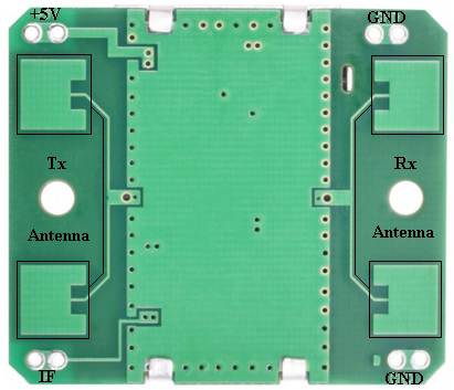
 Design with HB100 10.525 GHz Doppler Sensor in Cirkit Designer
Introduction
The HB100 is a microwave Doppler radar sensor that operates at a frequency of 10.525 GHz. It is designed to detect motion and measure the speed of moving objects by emitting microwave signals and analyzing the frequency shift caused by the Doppler effect. This compact and reliable sensor is widely used in applications such as security systems, automotive speed detection, robotics, and industrial automation.
Explore Projects Built with HB100 10.525 GHz Doppler Sensor
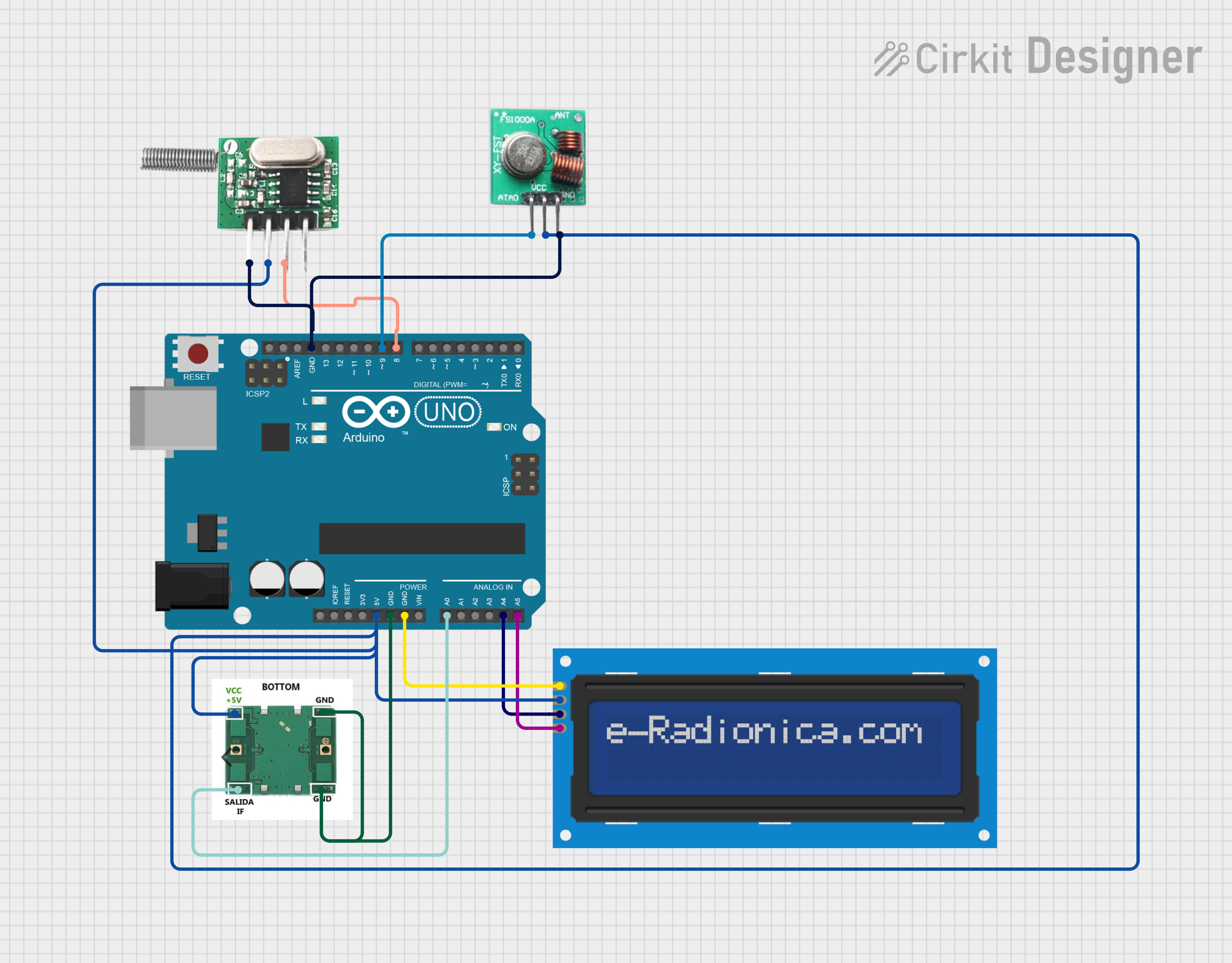 Open Project in Cirkit Designer
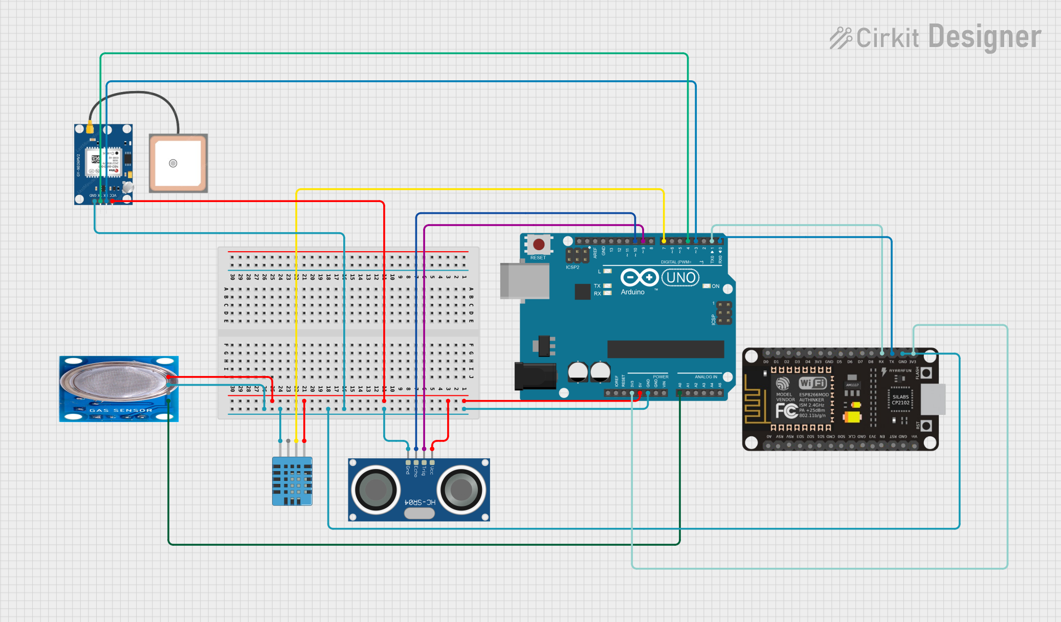 Open Project in Cirkit Designer
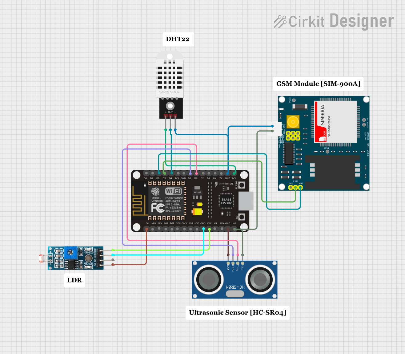 Open Project in Cirkit Designer
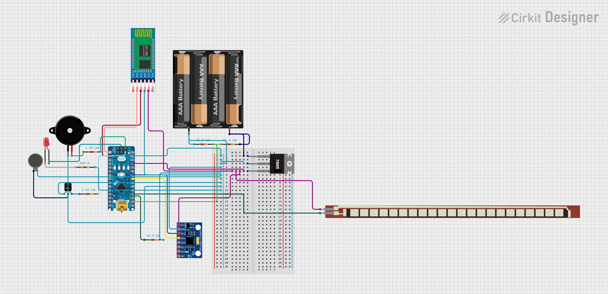 Open Project in Cirkit Designer
Explore Projects Built with HB100 10.525 GHz Doppler Sensor
Open Project in Cirkit DesignerOpen Project in Cirkit DesignerOpen Project in Cirkit DesignerOpen Project in Cirkit DesignerCommon Applications:
- Motion detection in security systems
- Speed measurement in automotive systems
- Object detection in robotics
- Industrial automation for monitoring moving machinery
Technical Specifications
The HB100 Doppler sensor is a highly efficient and versatile component. Below are its key technical details:
Key Specifications:
| Parameter | Value |
|---|---|
| Operating Frequency | 10.525 GHz ± 25 MHz |
| Operating Voltage | 4.75 V to 5.25 V |
| Operating Current | 30 mA (typical) |
| Output Signal | IF signal (Doppler shift) |
| Detection Range | Up to 20 meters (line of sight) |
| Beam Angle | 80° (horizontal), 34° (vertical) |
| Operating Temperature | -20°C to +75°C |
| Dimensions | 46 mm x 38 mm x 8 mm |
Pin Configuration:
The HB100 sensor has a simple pinout for easy integration into circuits. Below is the pin configuration:
| Pin Number | Pin Name | Description |
|---|---|---|
| 1 | VCC | Power supply input (4.75 V to 5.25 V) |
| 2 | GND | Ground connection |
| 3 | IF Output | Intermediate frequency output (Doppler signal) |
Usage Instructions
The HB100 Doppler sensor is straightforward to use in motion detection and speed measurement applications. Below are the steps and considerations for integrating it into a circuit:
Circuit Integration:
- Power Supply: Connect the VCC pin to a regulated 5V power supply and the GND pin to the ground.
- Signal Output: The IF Output pin provides the Doppler signal, which can be connected to an amplifier or microcontroller for processing.
- Amplification: Since the IF signal is weak, it is recommended to use an operational amplifier (e.g., LM358) to amplify the signal before further processing.
- Microcontroller Interface: The amplified signal can be fed into an ADC (Analog-to-Digital Converter) pin of a microcontroller, such as an Arduino UNO, for analysis.
Arduino UNO Example Code:
Below is an example of how to use the HB100 sensor with an Arduino UNO to detect motion:
// HB100 Doppler Sensor Example Code
// This code reads the amplified IF signal from the HB100 sensor and detects motion.

const int sensorPin = A0; // Analog pin connected to the amplified IF signal
int sensorValue = 0;      // Variable to store the sensor reading

void setup() {
  Serial.begin(9600); // Initialize serial communication for debugging
  pinMode(sensorPin, INPUT); // Set the sensor pin as input
}

void loop() {
  sensorValue = analogRead(sensorPin); // Read the sensor's output signal

  // Check if the signal exceeds a threshold (indicating motion)
  if (sensorValue > 512) {
    Serial.println("Motion detected!"); // Print motion detection message
  } else {
    Serial.println("No motion."); // Print no motion message
  }

  delay(100); // Small delay for stability
}
Important Considerations:
- Amplification: Ensure the IF signal is properly amplified for accurate detection.
- Placement: Place the sensor in a location with minimal obstructions for optimal performance.
- Interference: Avoid placing the sensor near other devices operating at similar frequencies to reduce interference.
- Power Supply: Use a stable and noise-free power supply to ensure reliable operation.
Troubleshooting and FAQs
Common Issues and Solutions:
No Output Signal:
- Cause: Incorrect wiring or insufficient power supply.
- Solution: Verify the connections and ensure the VCC pin receives a stable 5V supply.
Weak or No Detection:
- Cause: Insufficient amplification of the IF signal.
- Solution: Use an operational amplifier to boost the signal before feeding it to the microcontroller.
False Positives:
- Cause: Environmental interference or noise.
- Solution: Shield the sensor from external RF sources and use filtering techniques in the circuit.
Short Detection Range:
- Cause: Obstructions or improper placement.
- Solution: Ensure the sensor has a clear line of sight and is positioned correctly.
FAQs:
Q1: Can the HB100 detect stationary objects?
A1: No, the HB100 relies on the Doppler effect, which requires motion to generate a frequency shift.
Q2: What is the maximum detection range of the HB100?
A2: The sensor can detect motion up to 20 meters in a clear line of sight.
Q3: Can the HB100 be used outdoors?
A3: Yes, but it should be protected from extreme weather conditions and direct exposure to water.
Q4: How do I process the IF signal for speed measurement?
A4: The frequency of the IF signal corresponds to the speed of the moving object. Use an FFT (Fast Fourier Transform) algorithm or frequency counter to analyze the signal.
By following this documentation, users can effectively integrate and troubleshoot the HB100 Doppler sensor in their projects.