Cirkit Designer Logo
Cirkit Designer
Your all-in-one circuit design IDE
Home / 
Component Documentation

How to Use HDR 5V/15W/2.4A: Examples, Pinouts, and Specs

Image of HDR 5V/15W/2.4A
Cirkit Designer LogoDesign with HDR 5V/15W/2.4A in Cirkit Designer

Introduction

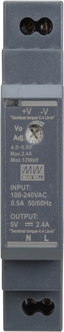
The HDR-15-24 by Mean Well is a high-density power supply module designed to deliver a stable 5V DC output with a maximum power rating of 15W and a current capacity of 2.4A. This compact and efficient module is ideal for powering a wide range of electronic devices, including microcontrollers, sensors, and small appliances. Its robust design ensures reliable performance in both industrial and consumer applications.

Explore Projects Built with HDR 5V/15W/2.4A

Use Cirkit Designer to design, explore, and prototype these projects online. Some projects support real-time simulation. Click "Open Project" to start designing instantly!
Battery-Powered USB Charger with LED Indicator and DC Motor
Image of Copy of Hand Crank mobile charger : A project utilizing HDR 5V/15W/2.4A in a practical application
This circuit converts AC power to DC using a bridge rectifier and regulates the voltage to 5V with a 7805 voltage regulator. It powers a USB port and indicates power status with an LED, while also providing a charging interface through a multi-charging cable.
Cirkit Designer LogoOpen Project in Cirkit Designer
12V to 5V Power Supply with LED Indicator and Push Switch
Image of Power Supply LVCO: A project utilizing HDR 5V/15W/2.4A in a practical application
This circuit is a 12V to 5V regulated power supply with an LED indicator. It uses a 5408 diode for reverse polarity protection, an LM340T5 7805 voltage regulator to step down the voltage to 5V, and a push switch to control the LED indicator. The circuit also includes capacitors for filtering and a resistor to limit the current through the LED.
Cirkit Designer LogoOpen Project in Cirkit Designer
Dual 5V Power Supply Distribution Circuit with Toggle Switch Control
Image of rfdriver: A project utilizing HDR 5V/15W/2.4A in a practical application
This circuit consists of two 5V 5A power supplies connected to an AC wall plug point, providing DC output through a 12-way connector. The ground connections from both power supplies are interconnected and also connected to the ground pins of two toggle switches. The DC outputs from the power supplies are separately connected to different pins on the 12-way connector, with each power supply output being switchable via one of the toggle switches.
Cirkit Designer LogoOpen Project in Cirkit Designer
USB-Powered DC Gear Motor with LED Indicator
Image of Hand Crank mobile charger : A project utilizing HDR 5V/15W/2.4A in a practical application
This circuit appears to be a power supply unit with a bridge rectifier connected to a DC gear motor, indicating it is designed to convert AC to DC power for the motor. An electrolytic capacitor is used for smoothing the DC output, and a 7805 voltage regulator is included to provide a stable 5V output. Additionally, there is an LED with a series resistor, likely serving as a power indicator light.
Cirkit Designer LogoOpen Project in Cirkit Designer

Explore Projects Built with HDR 5V/15W/2.4A

Use Cirkit Designer to design, explore, and prototype these projects online. Some projects support real-time simulation. Click "Open Project" to start designing instantly!
Image of Copy of Hand Crank mobile charger : A project utilizing HDR 5V/15W/2.4A in a practical application
Battery-Powered USB Charger with LED Indicator and DC Motor
This circuit converts AC power to DC using a bridge rectifier and regulates the voltage to 5V with a 7805 voltage regulator. It powers a USB port and indicates power status with an LED, while also providing a charging interface through a multi-charging cable.
Cirkit Designer LogoOpen Project in Cirkit Designer
Image of Power Supply LVCO: A project utilizing HDR 5V/15W/2.4A in a practical application
12V to 5V Power Supply with LED Indicator and Push Switch
This circuit is a 12V to 5V regulated power supply with an LED indicator. It uses a 5408 diode for reverse polarity protection, an LM340T5 7805 voltage regulator to step down the voltage to 5V, and a push switch to control the LED indicator. The circuit also includes capacitors for filtering and a resistor to limit the current through the LED.
Cirkit Designer LogoOpen Project in Cirkit Designer
Image of rfdriver: A project utilizing HDR 5V/15W/2.4A in a practical application
Dual 5V Power Supply Distribution Circuit with Toggle Switch Control
This circuit consists of two 5V 5A power supplies connected to an AC wall plug point, providing DC output through a 12-way connector. The ground connections from both power supplies are interconnected and also connected to the ground pins of two toggle switches. The DC outputs from the power supplies are separately connected to different pins on the 12-way connector, with each power supply output being switchable via one of the toggle switches.
Cirkit Designer LogoOpen Project in Cirkit Designer
Image of Hand Crank mobile charger : A project utilizing HDR 5V/15W/2.4A in a practical application
USB-Powered DC Gear Motor with LED Indicator
This circuit appears to be a power supply unit with a bridge rectifier connected to a DC gear motor, indicating it is designed to convert AC to DC power for the motor. An electrolytic capacitor is used for smoothing the DC output, and a 7805 voltage regulator is included to provide a stable 5V output. Additionally, there is an LED with a series resistor, likely serving as a power indicator light.
Cirkit Designer LogoOpen Project in Cirkit Designer

Common Applications

  • Powering microcontroller boards (e.g., Arduino, Raspberry Pi)
  • Supplying power to sensors and actuators in IoT systems
  • Driving small DC motors or LED strips
  • Industrial control systems and automation
  • General-purpose DC power supply for electronic projects

Technical Specifications

Key Technical Details

Parameter Value
Manufacturer Mean Well
Model Number HDR-15-24
Input Voltage Range 85-264 VAC / 120-370 VDC
Output Voltage 5V DC
Maximum Output Current 2.4A
Maximum Output Power 15W
Efficiency Up to 85%
Operating Temperature -30°C to +70°C
Dimensions 17.5 x 90 x 54.5 mm
Mounting Type DIN Rail
Protection Features Overload, Overvoltage, Short Circuit

Pin Configuration and Descriptions

The HDR-15-24 module features screw terminal connections for input and output. Below is the pin configuration:

Pin Number Label Description
1 L AC Line Input (Live)
2 N AC Neutral Input
3 -V DC Output Negative (-)
4 +V DC Output Positive (+)
5 Ground (GND) Earth Ground (optional for safety)

Usage Instructions

How to Use the HDR-15-24 in a Circuit

  1. Mounting: Secure the HDR-15-24 module onto a DIN rail in your enclosure or panel.
  2. Input Connection:
    • Connect the AC live wire to the L terminal.
    • Connect the AC neutral wire to the N terminal.
    • Optionally, connect the Earth Ground wire to the Ground (GND) terminal for safety.
  3. Output Connection:
    • Connect the +V terminal to the positive input of your load.
    • Connect the -V terminal to the negative input of your load.
  4. Power On: Once all connections are secure, supply AC power to the module. The module will convert the AC input to a stable 5V DC output.

Important Considerations and Best Practices

  • Ensure the input voltage is within the specified range (85-264 VAC).
  • Do not exceed the maximum output current of 2.4A to avoid triggering the overload protection.
  • Use appropriately rated wires for both input and output connections.
  • For safety, always disconnect the power supply before making any wiring changes.
  • If using the HDR-15-24 with sensitive electronics, consider adding a capacitor across the output terminals to reduce noise.

Example: Using HDR-15-24 with an Arduino UNO

The HDR-15-24 can be used to power an Arduino UNO directly via its 5V pin. Below is an example circuit and Arduino code:

Circuit Diagram

  1. Connect the +V terminal of the HDR-15-24 to the 5V pin of the Arduino UNO.
  2. Connect the -V terminal of the HDR-15-24 to the GND pin of the Arduino UNO.

Arduino Code

// Example code to blink an LED connected to pin 13 of the Arduino UNO
// Ensure the HDR-15-24 is providing a stable 5V to the Arduino

void setup() {
  pinMode(13, OUTPUT); // Set pin 13 as an output
}

void loop() {
  digitalWrite(13, HIGH); // Turn the LED on
  delay(1000);            // Wait for 1 second
  digitalWrite(13, LOW);  // Turn the LED off
  delay(1000);            // Wait for 1 second
}

Troubleshooting and FAQs

Common Issues and Solutions

Issue Possible Cause Solution
No output voltage Incorrect wiring or no AC input Verify input connections and AC power.
Output voltage fluctuates Overload or unstable input voltage Reduce load or stabilize input voltage.
Module overheats Exceeding power or current limits Ensure load is within 15W/2.4A limits.
Device not powering on Loose connections or faulty wiring Check all connections and tighten screws.

FAQs

  1. Can the HDR-15-24 power multiple devices simultaneously?

    • Yes, as long as the total current draw does not exceed 2.4A.
  2. Is the HDR-15-24 suitable for outdoor use?

    • No, the module is not weatherproof. Use it in a dry, indoor environment.
  3. What happens if the load exceeds 2.4A?

    • The overload protection will activate, shutting down the output to protect the module.
  4. Can I use the HDR-15-24 with a DC input?

    • Yes, the module supports a DC input range of 120-370 VDC.

By following this documentation, users can effectively integrate the HDR-15-24 into their projects and ensure reliable operation.