
How to Use Adafruit Metro RP2040: Examples, Pinouts, and Specs
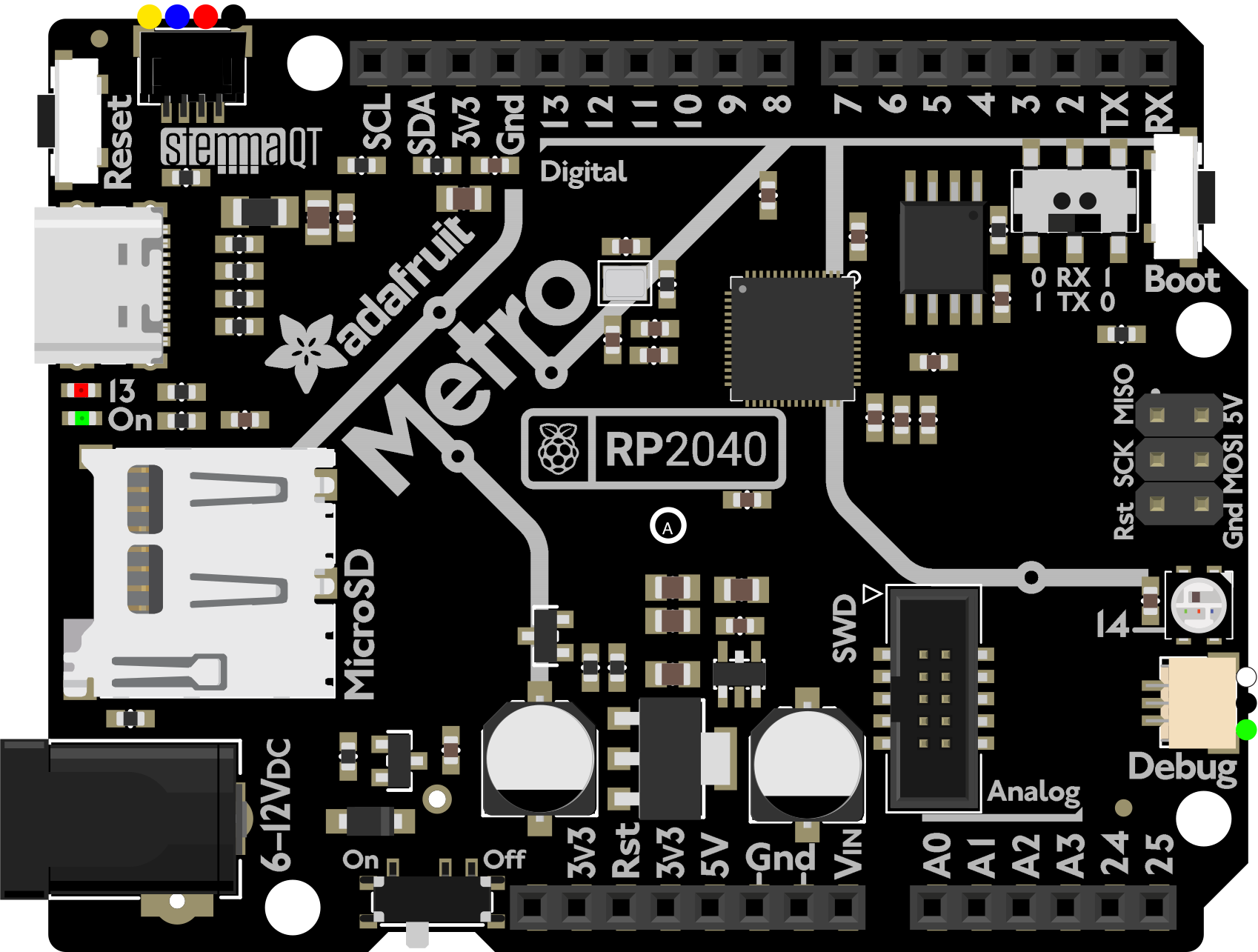
 Design with Adafruit Metro RP2040 in Cirkit Designer
Introduction
The Adafruit Metro RP2040 (Manufacturer Part ID: 5786) is a versatile microcontroller board powered by the Raspberry Pi RP2040 chip. It is designed for hobbyists, educators, and professionals who need a powerful yet easy-to-use development platform. The board features USB-C connectivity, a wide array of GPIO pins, and compatibility with the Arduino IDE, CircuitPython, and MicroPython, making it an excellent choice for a variety of projects.
Explore Projects Built with Adafruit Metro RP2040
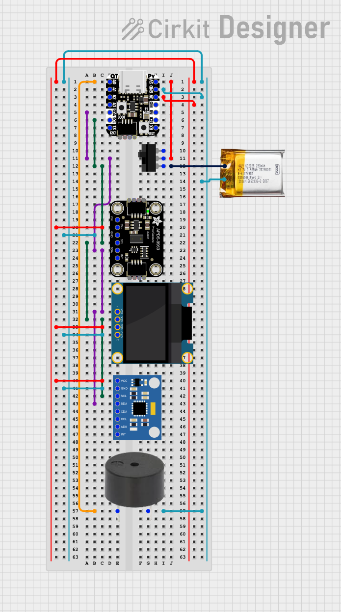 Open Project in Cirkit Designer
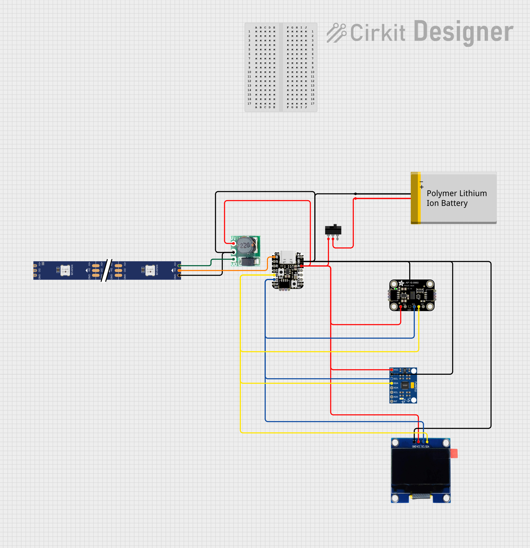 Open Project in Cirkit Designer
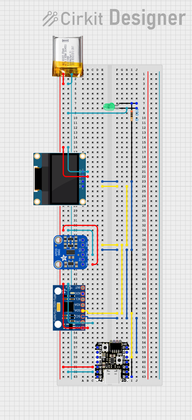 Open Project in Cirkit Designer
 Open Project in Cirkit Designer
Explore Projects Built with Adafruit Metro RP2040
Open Project in Cirkit DesignerOpen Project in Cirkit DesignerOpen Project in Cirkit DesignerOpen Project in Cirkit DesignerCommon Applications and Use Cases
- Robotics and automation projects
- IoT (Internet of Things) devices
- Prototyping and hardware development
- Educational tools for learning programming and electronics
- Wearable technology and interactive art installations
Technical Specifications
The Adafruit Metro RP2040 is packed with features that make it a robust and flexible microcontroller board. Below are its key technical details:
Key Technical Details
- Microcontroller: Raspberry Pi RP2040 (Dual-core ARM Cortex-M0+ @ 133 MHz)
- Flash Memory: 16 MB QSPI Flash
- RAM: 264 KB SRAM
- USB Connectivity: USB-C for programming and power
- GPIO Pins: 21 (including analog inputs, I2C, SPI, UART)
- Power Supply: 5V via USB-C or external power supply
- Operating Voltage: 3.3V logic level
- Dimensions: 71.1 mm x 53.3 mm
- Weight: 22 grams
Pin Configuration and Descriptions
The Adafruit Metro RP2040 features a standard pinout for easy integration into projects. Below is the pin configuration:
| Pin | Name | Description |
|---|---|---|
| 1 | 3V3 | 3.3V power output |
| 2 | GND | Ground |
| 3 | A0 (GP26) | Analog input or GPIO |
| 4 | A1 (GP27) | Analog input or GPIO |
| 5 | A2 (GP28) | Analog input or GPIO |
| 6 | SDA (GP0) | I2C data line |
| 7 | SCL (GP1) | I2C clock line |
| 8 | TX (GP4) | UART transmit |
| 9 | RX (GP5) | UART receive |
| 10 | SCK (GP18) | SPI clock line |
| 11 | MOSI (GP19) | SPI master out, slave in |
| 12 | MISO (GP16) | SPI master in, slave out |
| 13 | D13 (GP25) | Built-in LED |
| 14-21 | GPIO Pins | General-purpose input/output pins |
Usage Instructions
The Adafruit Metro RP2040 is designed to be user-friendly and compatible with multiple programming environments. Below are the steps to get started and important considerations for using the board.
How to Use the Component in a Circuit
- Power the Board: Connect the board to your computer or a power source using a USB-C cable.
- Install Software:
- For Arduino IDE: Install the RP2040 board package via the Arduino Boards Manager.
- For CircuitPython: Download and flash the CircuitPython firmware from Adafruit's website.
- Connect Peripherals: Use jumper wires to connect sensors, actuators, or other components to the GPIO pins.
- Write Code: Use your preferred IDE (Arduino IDE, Thonny, or Mu Editor) to write and upload code to the board.
Important Considerations and Best Practices
- Voltage Levels: The GPIO pins operate at 3.3V logic. Avoid connecting 5V signals directly to the pins to prevent damage.
- Power Supply: Ensure the board is powered via USB-C or an external 5V power source.
- Pin Usage: Refer to the pin configuration table to avoid conflicts when using multiple peripherals.
- Firmware Updates: Keep the firmware updated to access the latest features and bug fixes.
Example Code for Arduino IDE
Below is an example code snippet to blink the built-in LED on pin D13:
// Blink the built-in LED on the Adafruit Metro RP2040
// The LED is connected to GPIO pin 25 (D13)

void setup() {
  pinMode(25, OUTPUT); // Set GPIO 25 (D13) as an output
}

void loop() {
  digitalWrite(25, HIGH); // Turn the LED on
  delay(1000);            // Wait for 1 second
  digitalWrite(25, LOW);  // Turn the LED off
  delay(1000);            // Wait for 1 second
}
Troubleshooting and FAQs
Common Issues Users Might Face
- Board Not Recognized by Computer:
- Ensure the USB-C cable is data-capable (not just a charging cable).
- Check that the board is in bootloader mode by holding the BOOTSEL button while connecting it to your computer.
- Code Upload Fails:
- Verify that the correct board and port are selected in the Arduino IDE.
- Ensure no other program is accessing the board's serial port.
- Peripherals Not Working:
- Double-check wiring and connections.
- Confirm that the correct GPIO pins are being used in the code.
Solutions and Tips for Troubleshooting
- Reset the Board: Press the RESET button to restart the board and clear any temporary issues.
- Check Power Supply: Ensure the board is receiving sufficient power (5V via USB-C or external source).
- Consult Documentation: Refer to Adafruit's official guides and forums for additional support.
By following this documentation, users can effectively utilize the Adafruit Metro RP2040 for a wide range of projects and applications.