How to Use MAPPI32: Examples, Pinouts, and Specs
Introduction
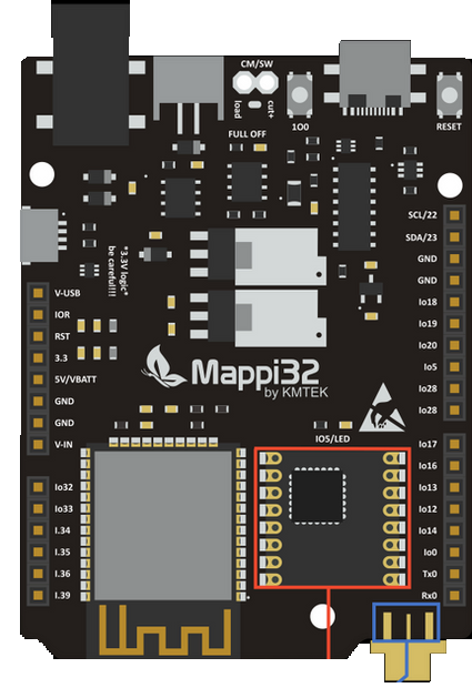
The MAPPI32, manufactured by KMTEK (Part ID: UNO), is a programmable analog signal processing integrated circuit (IC) designed for high-precision applications. It is equipped with multiple input channels, programmable gain, and filtering capabilities, making it ideal for signal conditioning and data acquisition tasks. The MAPPI32 is widely used in industrial automation, medical instrumentation, and scientific research, where accurate and reliable signal processing is critical.
Explore Projects Built with MAPPI32
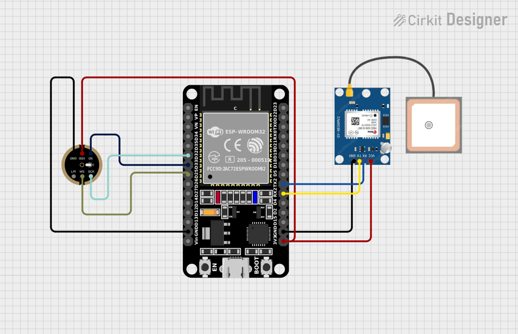
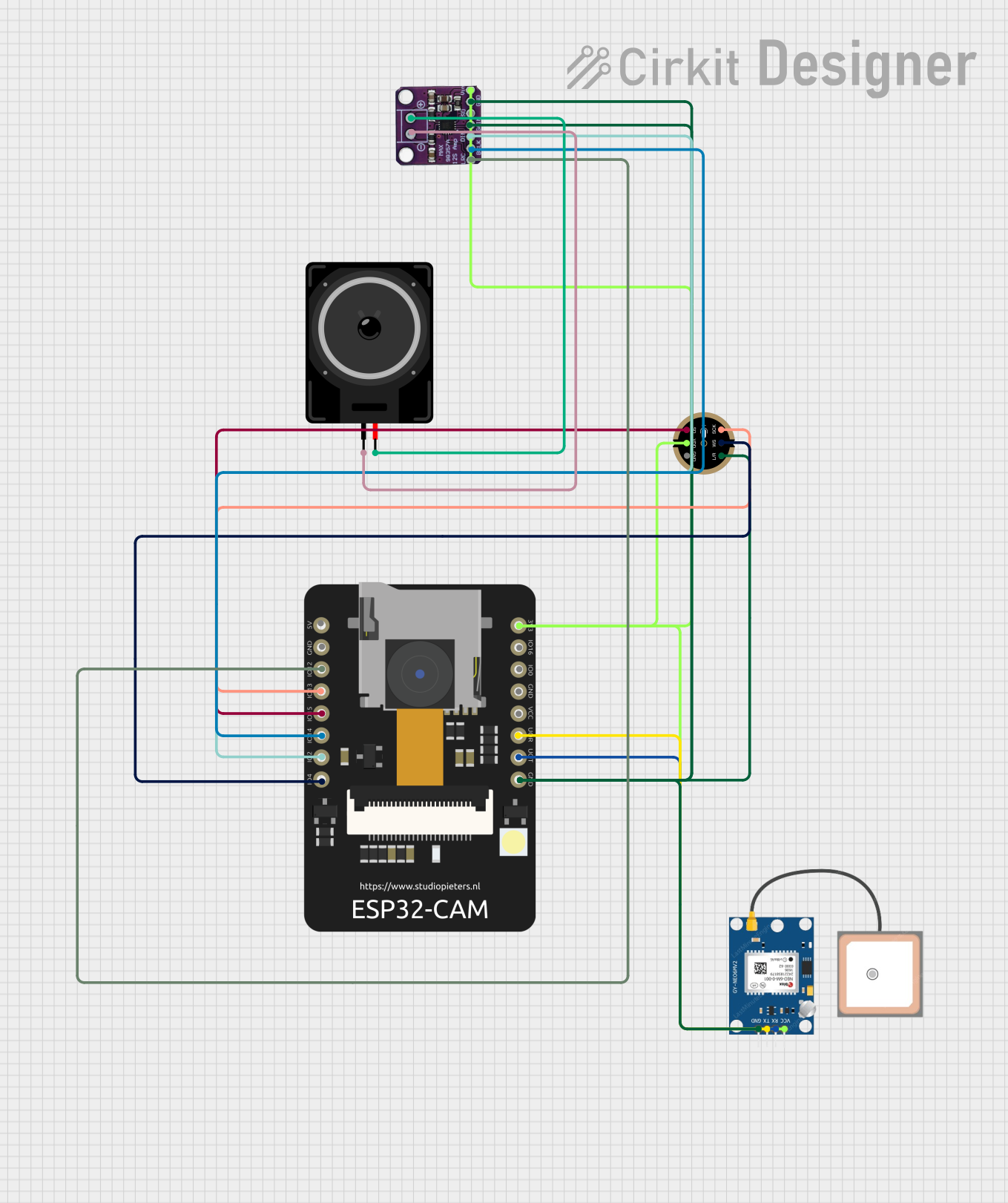
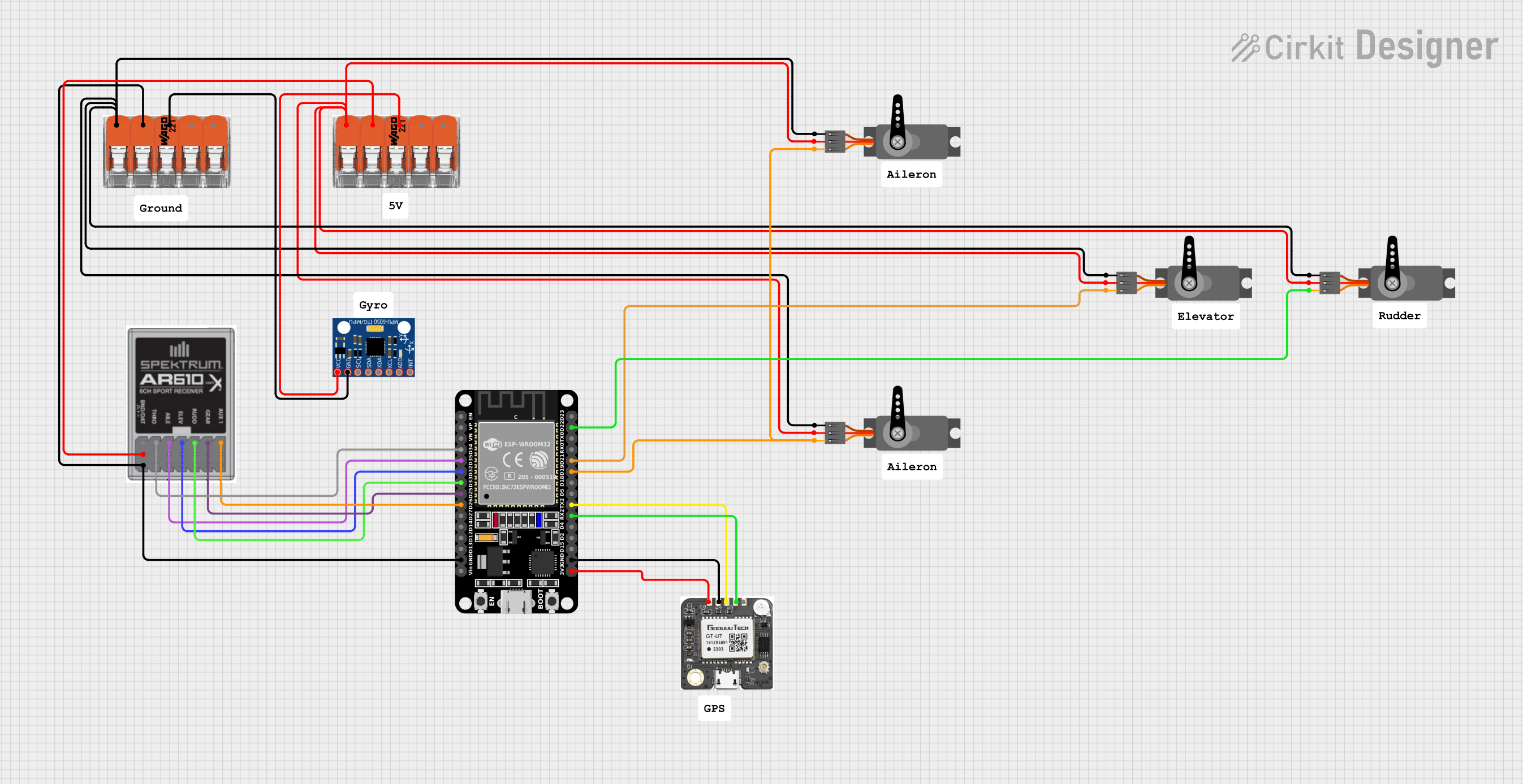
Explore Projects Built with MAPPI32
Common Applications
- Signal conditioning for sensors (e.g., temperature, pressure, and strain gauges)
- Data acquisition systems
- Industrial process control
- Medical devices requiring high-precision analog signal processing
- Scientific instrumentation
Technical Specifications
Key Technical Details
| Parameter | Value |
|---|---|
| Supply Voltage | 3.3V to 5V |
| Input Channels | 4 differential or 8 single-ended |
| Programmable Gain Range | 1x to 128x |
| Input Impedance | >10 MΩ |
| Bandwidth | 0.1 Hz to 100 kHz (programmable) |
| Output Format | Analog or SPI digital output |
| Operating Temperature Range | -40°C to +85°C |
| Package Type | 28-pin TSSOP |
Pin Configuration and Descriptions
| Pin Number | Pin Name | Description |
|---|---|---|
| 1 | VDD | Positive power supply (3.3V to 5V) |
| 2 | GND | Ground |
| 3-10 | IN1+ to IN4- | Differential or single-ended input channels |
| 11 | REF+ | Positive reference voltage input |
| 12 | REF- | Negative reference voltage input |
| 13 | SPI_MOSI | SPI Master Out Slave In (data input) |
| 14 | SPI_MISO | SPI Master In Slave Out (data output) |
| 15 | SPI_SCK | SPI clock |
| 16 | SPI_CS | SPI chip select |
| 17 | OUT | Analog output (filtered signal) |
| 18 | RESET | Active-low reset pin |
| 19-28 | NC | No connection (reserved for future use) |
Usage Instructions
How to Use the MAPPI32 in a Circuit
- Power Supply: Connect the VDD pin to a stable 3.3V or 5V power source and the GND pin to ground.
- Input Configuration:
- For differential inputs, connect the signal source to the IN+ and IN- pins of the desired channel.
- For single-ended inputs, connect the signal source to the IN+ pin and ground the corresponding IN- pin.
- Reference Voltage: Provide a stable reference voltage to the REF+ and REF- pins. This determines the input range.
- SPI Communication:
- Connect the SPI_MOSI, SPI_MISO, SPI_SCK, and SPI_CS pins to the corresponding pins on your microcontroller or processor.
- Use SPI to configure the gain, bandwidth, and filtering settings.
- Output:
- For analog output, read the processed signal from the OUT pin.
- For digital output, use the SPI interface to retrieve the processed data.
Important Considerations and Best Practices
- Use decoupling capacitors (e.g., 0.1 µF and 10 µF) near the VDD pin to ensure stable operation.
- Avoid long wires for input signals to minimize noise and signal degradation.
- Ensure the reference voltage is stable and noise-free for accurate measurements.
- Configure the gain and bandwidth settings based on the input signal characteristics to avoid saturation or distortion.
- If using the SPI interface, ensure proper termination and clock speed settings to avoid communication errors.
Example: Connecting MAPPI32 to an Arduino UNO
Below is an example of how to configure the MAPPI32 using an Arduino UNO via SPI:
#include <SPI.h>

// Define SPI pins for MAPPI32
const int chipSelectPin = 10; // Chip select pin for MAPPI32

void setup() {
  // Initialize SPI communication
  SPI.begin();
  pinMode(chipSelectPin, OUTPUT);
  digitalWrite(chipSelectPin, HIGH); // Set CS pin high initially

  // Configure MAPPI32 settings
  configureMAPPI32();
}

void loop() {
  // Example: Read processed data from MAPPI32
  int processedData = readMAPPI32();
  Serial.println(processedData); // Print the data to the serial monitor
  delay(1000); // Wait for 1 second
}

void configureMAPPI32() {
  digitalWrite(chipSelectPin, LOW); // Select MAPPI32
  SPI.transfer(0x01); // Example command to set gain
  SPI.transfer(0x80); // Example value for gain (e.g., 128x)
  digitalWrite(chipSelectPin, HIGH); // Deselect MAPPI32
}

int readMAPPI32() {
  digitalWrite(chipSelectPin, LOW); // Select MAPPI32
  SPI.transfer(0x02); // Example command to read data
  int data = SPI.transfer(0x00); // Read data from MAPPI32
  digitalWrite(chipSelectPin, HIGH); // Deselect MAPPI32
  return data;
}
Notes:
- Replace the example SPI commands (
0x01,0x02, etc.) with the actual commands from the MAPPI32 datasheet. - Ensure the Arduino UNO is powered with a stable 5V supply when interfacing with the MAPPI32.
Troubleshooting and FAQs
Common Issues and Solutions
No Output Signal:
- Verify the power supply connections (VDD and GND).
- Check the reference voltage (REF+ and REF-) for stability.
- Ensure the input signal is within the expected range.
No SPI Communication:
- Confirm the SPI pins are correctly connected to the microcontroller.
- Check the SPI clock speed and ensure it matches the MAPPI32's requirements.
- Verify the chip select (CS) pin is toggling correctly.
Distorted or Saturated Output:
- Reduce the gain setting if the input signal is too large.
- Check for noise or interference in the input signal.
High Noise in Output:
- Use proper shielding and grounding techniques for the input signals.
- Add external filtering if necessary.
FAQs
Q: Can the MAPPI32 handle both AC and DC signals?
A: Yes, the MAPPI32 can process both AC and DC signals, but the bandwidth and gain settings should be configured accordingly.
Q: What is the maximum input voltage range?
A: The input voltage range depends on the reference voltage and gain settings. For example, with a 5V reference and 1x gain, the range is approximately ±5V.
Q: Can I use the MAPPI32 with a 3.3V microcontroller?
A: Yes, the MAPPI32 is compatible with 3.3V systems. Ensure the SPI voltage levels match the microcontroller's logic levels.
Q: How do I reset the MAPPI32?
A: Pull the RESET pin low for at least 10 µs to reset the device.