How to Use Screen: Examples, Pinouts, and Specs
Introduction
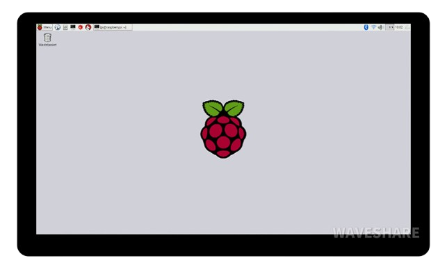
A screen is a display device that visually presents information, images, or video output from a computer or electronic device. Screens are essential components in modern electronics, enabling users to interact with devices through visual feedback. They come in various types, such as LCD, OLED, and LED, and are used in a wide range of applications.
Common applications and use cases include:
- Displaying graphical user interfaces (GUIs) in devices like smartphones, tablets, and computers.
- Visualizing data in embedded systems, such as temperature readings or sensor outputs.
- Presenting video content in entertainment systems.
- Providing feedback in industrial control systems and IoT devices.
Explore Projects Built with Screen
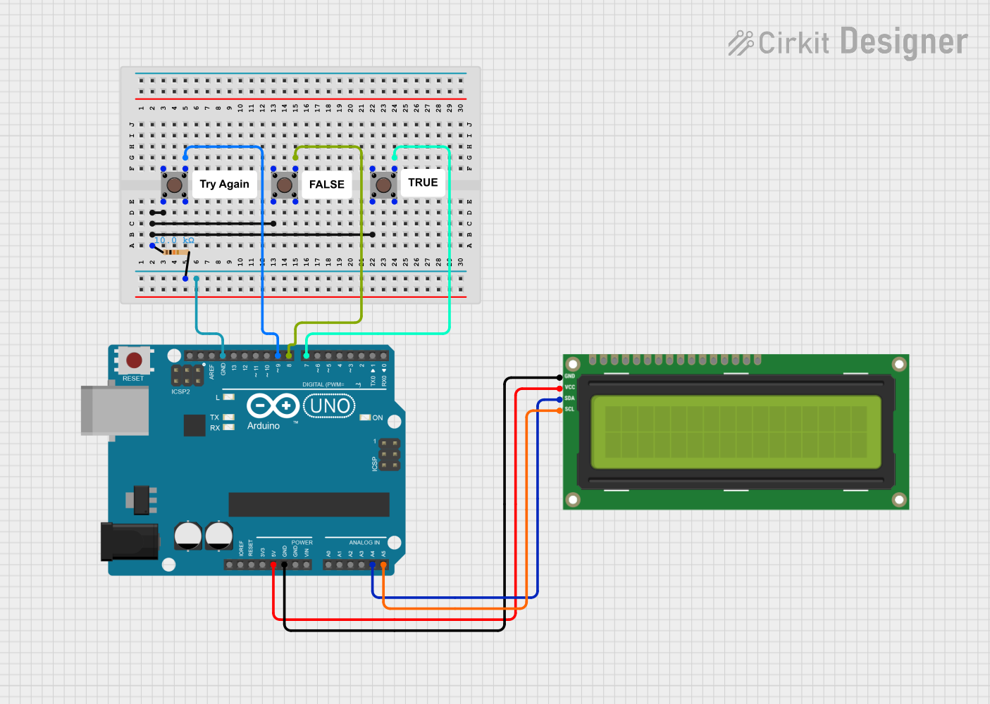

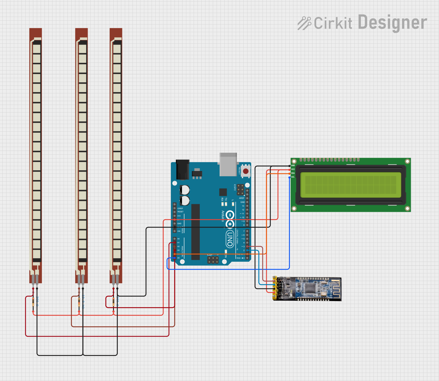
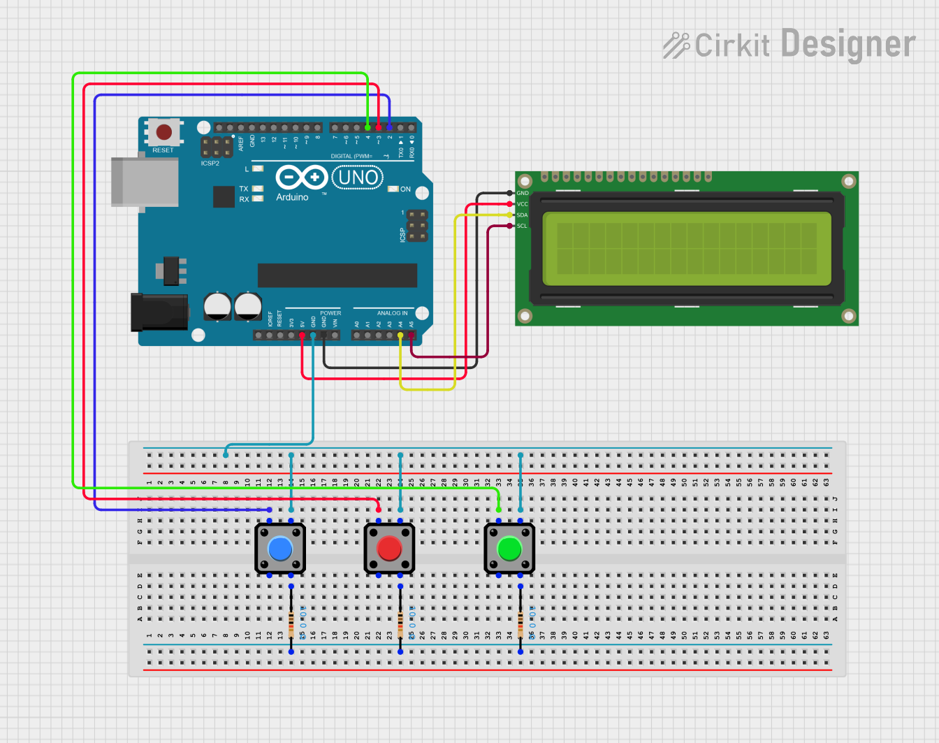
Explore Projects Built with Screen
Technical Specifications
The technical specifications of a screen can vary depending on its type and intended use. Below are general specifications for a typical LCD screen module commonly used in electronics projects:
General Specifications
| Parameter | Value |
|---|---|
| Display Type | LCD (Liquid Crystal Display) |
| Resolution | 128x64 pixels (example) |
| Operating Voltage | 3.3V - 5V |
| Current Consumption | ~20mA (varies by model) |
| Interface | SPI/I2C/Parallel |
| Backlight | LED (adjustable brightness) |
| Viewing Angle | ~160° |
| Operating Temperature | -20°C to 70°C |
Pin Configuration
Below is an example pin configuration for a 16-pin LCD screen module:
| Pin Number | Pin Name | Description |
|---|---|---|
| 1 | VSS | Ground (0V) |
| 2 | VDD | Power supply (3.3V or 5V) |
| 3 | VO | Contrast adjustment (connect to potentiometer) |
| 4 | RS | Register Select (Command/Data selection) |
| 5 | RW | Read/Write control (set to LOW for write mode) |
| 6 | E | Enable signal (triggers data read/write) |
| 7-14 | D0-D7 | Data pins (used for parallel communication) |
| 15 | LED+ | Backlight anode (connect to power via resistor) |
| 16 | LED- | Backlight cathode (connect to ground) |
Usage Instructions
How to Use the Screen in a Circuit
- Power the Screen: Connect the VSS pin to ground and the VDD pin to a 3.3V or 5V power source, depending on the screen's specifications.
- Adjust Contrast: Connect the VO pin to the wiper of a 10kΩ potentiometer. Adjust the potentiometer to set the desired contrast level.
- Connect Control Pins:
- Connect the RS pin to a digital output pin on your microcontroller.
- Set the RW pin to ground for write mode.
- Connect the E pin to another digital output pin on your microcontroller.
- Data Pins: For parallel communication, connect D0-D7 to the microcontroller's digital pins. For SPI or I2C communication, refer to the screen's datasheet for the appropriate connections.
- Backlight: Connect the LED+ pin to a power source through a current-limiting resistor (e.g., 220Ω). Connect the LED- pin to ground.
Example Code for Arduino UNO
Below is an example of how to use a 16x2 LCD screen with an Arduino UNO using the LiquidCrystal library:
#include <LiquidCrystal.h>

// Initialize the library with the numbers of the interface pins
LiquidCrystal lcd(12, 11, 5, 4, 3, 2);

void setup() {
  // Set up the LCD's number of columns and rows
  lcd.begin(16, 2);

  // Print a message to the LCD
  lcd.print("Hello, World!");
}

void loop() {
  // Set the cursor to column 0, line 1
  lcd.setCursor(0, 1);

  // Print the number of seconds since reset
  lcd.print(millis() / 1000);
}
Important Considerations and Best Practices
- Power Supply: Ensure the screen's operating voltage matches your circuit's power supply to avoid damage.
- Contrast Adjustment: Use a potentiometer to fine-tune the contrast for optimal visibility.
- Backlight Current: Use an appropriate resistor to limit the current through the backlight and prevent overheating.
- Communication Protocol: Verify the screen's communication protocol (SPI, I2C, or parallel) and configure your microcontroller accordingly.
Troubleshooting and FAQs
Common Issues and Solutions
Screen Does Not Turn On:
- Verify the power connections (VSS to ground, VDD to 3.3V or 5V).
- Check the backlight connections and resistor value.
No Display or Garbled Text:
- Ensure the contrast is properly adjusted using the potentiometer.
- Verify the data and control pin connections to the microcontroller.
- Check the code for correct initialization of the screen.
Flickering or Unstable Display:
- Ensure a stable power supply with minimal noise.
- Use decoupling capacitors (e.g., 0.1µF) near the power pins.
Backlight Not Working:
- Check the LED+ and LED- connections.
- Verify the current-limiting resistor value.
FAQs
Q: Can I use the screen with a 3.3V microcontroller?
A: Yes, most screens are compatible with 3.3V systems. However, check the datasheet to confirm voltage compatibility.
Q: How do I connect the screen using I2C?
A: For I2C-enabled screens, connect the SDA and SCL pins to the corresponding pins on your microcontroller. Use an I2C library to communicate with the screen.
Q: Why is the text on the screen faint or invisible?
A: This is likely due to incorrect contrast settings. Adjust the potentiometer connected to the VO pin.
Q: Can I use the screen without a backlight?
A: Yes, but the display may be difficult to read in low-light conditions. The backlight improves visibility.