Cirkit Designer Logo
Cirkit Designer
Your all-in-one circuit design IDE
Home / 
Component Documentation

How to Use MB102 Breadboard Power Supply Module 3.3V/5V: Examples, Pinouts, and Specs

Image of MB102 Breadboard Power Supply Module 3.3V/5V
Cirkit Designer LogoDesign with MB102 Breadboard Power Supply Module 3.3V/5V in Cirkit Designer

Introduction

The MB102 Breadboard Power Supply Module by CorpCo (Part ID: Uno) is a compact and versatile power supply solution designed specifically for breadboard-based prototyping. It provides stable output voltages of 3.3V and 5V, making it ideal for powering a wide range of electronic components and projects. This module is easy to use, fits snugly onto standard breadboards, and eliminates the need for bulky external power supplies.

Explore Projects Built with MB102 Breadboard Power Supply Module 3.3V/5V

Use Cirkit Designer to design, explore, and prototype these projects online. Some projects support real-time simulation. Click "Open Project" to start designing instantly!
Arduino UNO RFID Access Control System with LCD Feedback and Servo Operation
Image of door lock: A project utilizing MB102 Breadboard Power Supply Module 3.3V/5V in a practical application
This circuit features an Arduino UNO as the central microcontroller, interfaced with an RFID-RC522 module for RFID reading capabilities, and a 16x2 LCD screen with I2C for display. It also includes a 4x4 membrane matrix keypad for user input, a buzzer for audio feedback, and two Tower Pro SG90 servos for actuation. The MB102 Breadboard Power Supply Module provides power to the servos, while the Arduino powers the other components.
Cirkit Designer LogoOpen Project in Cirkit Designer
Battery-Powered 18650 Li-ion Charger with USB Output and Adjustable Voltage Regulator
Image of Breadboard: A project utilizing MB102 Breadboard Power Supply Module 3.3V/5V in a practical application
This circuit is a battery management and power supply system that uses three 3.7V batteries connected to a 3S 10A Li-ion 18650 Charger Protection Board Module for balanced charging and protection. The system includes a TP4056 Battery Charging Protection Module for additional charging safety, a Step Up Boost Power Converter to regulate and boost the voltage, and a USB regulator to provide a stable 5V output, controlled by a push switch.
Cirkit Designer LogoOpen Project in Cirkit Designer
Battery-Powered Arduino UNO and ESP-8266 Smart Controller with LCD and RTC
Image of Ogie Diagram: A project utilizing MB102 Breadboard Power Supply Module 3.3V/5V in a practical application
This circuit is a power management and control system that uses a 12V power supply and a 18650 Li-ion battery pack to provide a stable 5V output through a step-down buck converter. It includes an Arduino UNO, an ESP-8266 controller, a DS1307 RTC module, and a 20x4 I2C LCD display for monitoring and control purposes. The ULN2003A breakout board is used for driving higher current loads.
Cirkit Designer LogoOpen Project in Cirkit Designer
ESP8266 NodeMCU with LoRa and RS-485 Communication and Ethernet Connectivity
Image of Wiring Diagram LoRa: A project utilizing MB102 Breadboard Power Supply Module 3.3V/5V in a practical application
This circuit serves as a multi-protocol communication hub featuring two ESP8266 NodeMCUs for processing, each connected to a LoRa Ra-02 SX1278 for long-range wireless communication. One NodeMCU is also connected to an RS-485 module for serial communication and a W5500 Ethernet module for network connectivity, with MB102 modules supplying power.
Cirkit Designer LogoOpen Project in Cirkit Designer

Explore Projects Built with MB102 Breadboard Power Supply Module 3.3V/5V

Use Cirkit Designer to design, explore, and prototype these projects online. Some projects support real-time simulation. Click "Open Project" to start designing instantly!
Image of door lock: A project utilizing MB102 Breadboard Power Supply Module 3.3V/5V in a practical application
Arduino UNO RFID Access Control System with LCD Feedback and Servo Operation
This circuit features an Arduino UNO as the central microcontroller, interfaced with an RFID-RC522 module for RFID reading capabilities, and a 16x2 LCD screen with I2C for display. It also includes a 4x4 membrane matrix keypad for user input, a buzzer for audio feedback, and two Tower Pro SG90 servos for actuation. The MB102 Breadboard Power Supply Module provides power to the servos, while the Arduino powers the other components.
Cirkit Designer LogoOpen Project in Cirkit Designer
Image of Breadboard: A project utilizing MB102 Breadboard Power Supply Module 3.3V/5V in a practical application
Battery-Powered 18650 Li-ion Charger with USB Output and Adjustable Voltage Regulator
This circuit is a battery management and power supply system that uses three 3.7V batteries connected to a 3S 10A Li-ion 18650 Charger Protection Board Module for balanced charging and protection. The system includes a TP4056 Battery Charging Protection Module for additional charging safety, a Step Up Boost Power Converter to regulate and boost the voltage, and a USB regulator to provide a stable 5V output, controlled by a push switch.
Cirkit Designer LogoOpen Project in Cirkit Designer
Image of Ogie Diagram: A project utilizing MB102 Breadboard Power Supply Module 3.3V/5V in a practical application
Battery-Powered Arduino UNO and ESP-8266 Smart Controller with LCD and RTC
This circuit is a power management and control system that uses a 12V power supply and a 18650 Li-ion battery pack to provide a stable 5V output through a step-down buck converter. It includes an Arduino UNO, an ESP-8266 controller, a DS1307 RTC module, and a 20x4 I2C LCD display for monitoring and control purposes. The ULN2003A breakout board is used for driving higher current loads.
Cirkit Designer LogoOpen Project in Cirkit Designer
Image of Wiring Diagram LoRa: A project utilizing MB102 Breadboard Power Supply Module 3.3V/5V in a practical application
ESP8266 NodeMCU with LoRa and RS-485 Communication and Ethernet Connectivity
This circuit serves as a multi-protocol communication hub featuring two ESP8266 NodeMCUs for processing, each connected to a LoRa Ra-02 SX1278 for long-range wireless communication. One NodeMCU is also connected to an RS-485 module for serial communication and a W5500 Ethernet module for network connectivity, with MB102 modules supplying power.
Cirkit Designer LogoOpen Project in Cirkit Designer

Common Applications and Use Cases

  • Powering microcontrollers (e.g., Arduino, ESP32, Raspberry Pi Pico)
  • Supplying power to sensors, LEDs, and other low-power components
  • Prototyping and testing circuits on breadboards
  • Educational and hobbyist electronics projects

Technical Specifications

The following table outlines the key technical details of the MB102 Breadboard Power Supply Module:

Parameter Specification
Input Voltage 6.5V to 12V (via DC barrel jack)
Alternate Input 5V (via USB Type-A port)
Output Voltage Options 3.3V and 5V
Maximum Output Current 700mA (depending on input source)
Dimensions 53mm x 35mm x 20mm
Compatibility Standard 830-point breadboards

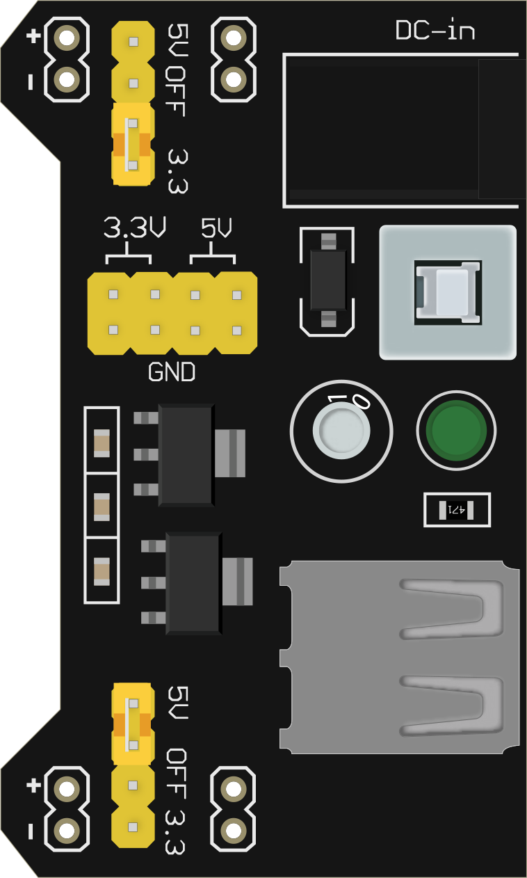
Pin Configuration and Descriptions

The MB102 module has several key pins and connectors. The table below describes their functions:

Pin/Connector Description
DC Barrel Jack Input for 6.5V to 12V DC power supply.
USB Type-A Port Alternate input for 5V power supply.
Power Switch Toggles the module ON or OFF.
Voltage Selector Jumper Selects the output voltage (3.3V or 5V) for each power rail.
Breadboard Pins Outputs 3.3V or 5V to the breadboard's power rails (left and right sides).
GND Pins Provides ground connections to the breadboard's ground rails.

Usage Instructions

How to Use the MB102 Power Supply Module in a Circuit

  1. Connect the Module to a Breadboard:

    • Align the module's pins with the power rails of a standard 830-point breadboard.
    • Gently press the module into place to ensure a secure connection.
  2. Provide Input Power:

    • Use a DC power adapter (6.5V to 12V) and connect it to the DC barrel jack.
    • Alternatively, connect a USB power source (5V) to the USB Type-A port.
  3. Set the Output Voltage:

    • Use the voltage selector jumpers to choose between 3.3V and 5V for each power rail.
    • Ensure the jumpers are securely placed in the desired position.
  4. Power On the Module:

    • Slide the power switch to the ON position.
    • Verify the power indicator LED lights up, confirming the module is operational.
  5. Connect Components:

    • Use the breadboard's power and ground rails to supply power to your circuit components.

Important Considerations and Best Practices

  • Input Voltage Range: Ensure the input voltage is within the specified range (6.5V to 12V). Exceeding this range may damage the module.
  • Current Limitations: The module can supply a maximum current of 700mA. Avoid overloading the module to prevent overheating or failure.
  • Voltage Selection: Double-check the voltage selector jumpers before connecting sensitive components to avoid accidental damage.
  • Heat Dissipation: If the module becomes warm during operation, ensure adequate ventilation to prevent overheating.

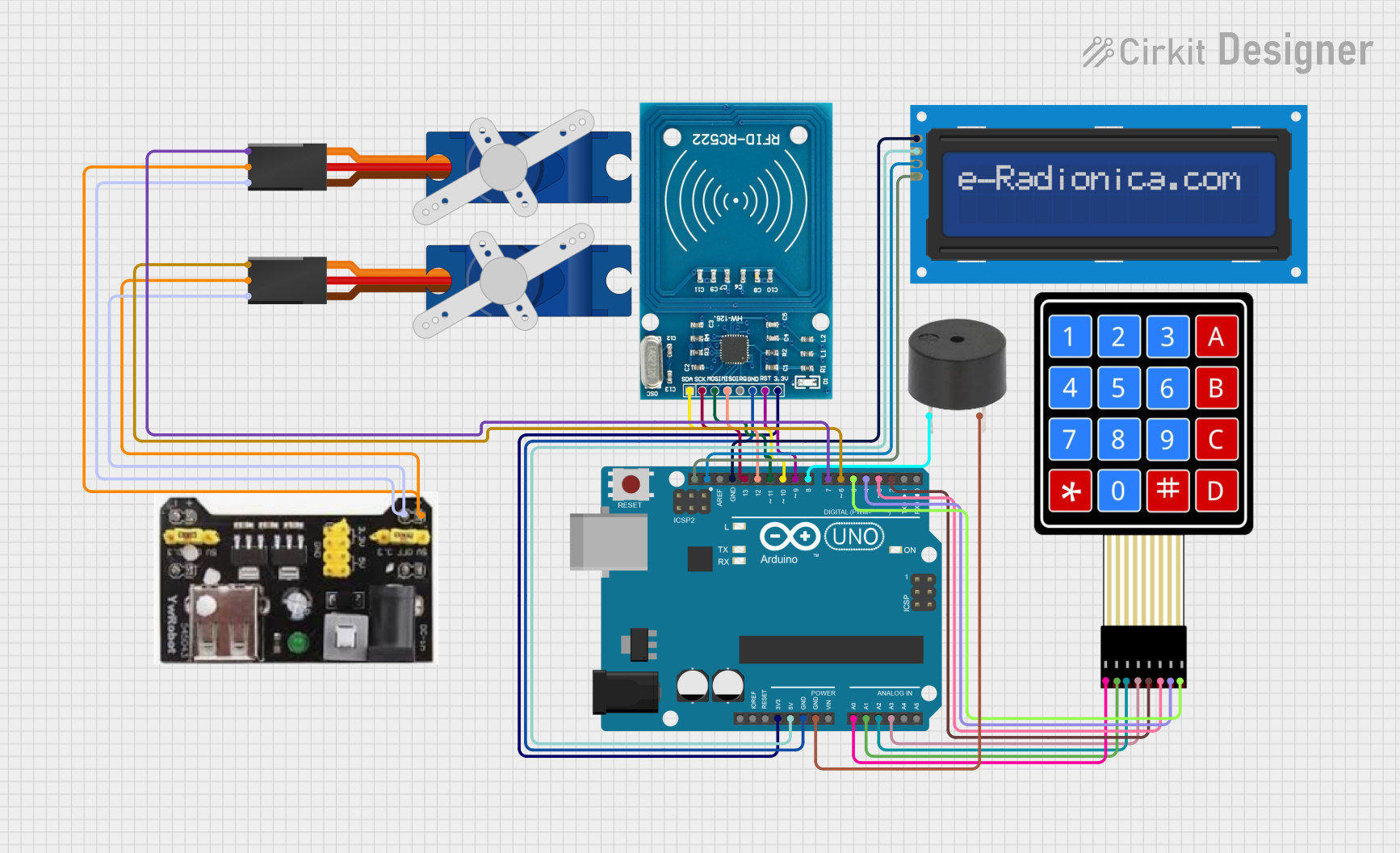
Example: Using the MB102 with an Arduino UNO

Below is an example of how to power an Arduino UNO using the MB102 module:

  1. Connect the MB102 module to the breadboard.
  2. Set the voltage selector jumper to 5V.
  3. Use jumper wires to connect the breadboard's 5V and GND rails to the Arduino UNO's 5V and GND pins, respectively.

Sample Arduino Code

// Example: Blink an LED using Arduino UNO powered by MB102 module

// Define the LED pin
const int ledPin = 13;

void setup() {
  pinMode(ledPin, OUTPUT); // Set the LED pin as an output
}

void loop() {
  digitalWrite(ledPin, HIGH); // Turn the LED on
  delay(1000);               // Wait for 1 second
  digitalWrite(ledPin, LOW);  // Turn the LED off
  delay(1000);               // Wait for 1 second
}

Troubleshooting and FAQs

Common Issues and Solutions

Issue Possible Cause Solution
Module does not power on Input voltage is too low or disconnected Verify the input voltage is within the 6.5V to 12V range or check USB power.
Output voltage is incorrect Voltage selector jumper is misconfigured Ensure the jumpers are set to the desired voltage (3.3V or 5V).
Components not receiving power Poor connection to the breadboard Ensure the module is securely connected to the breadboard.
Module overheats during operation Excessive current draw or poor ventilation Reduce the load or improve airflow around the module.

FAQs

  1. Can I use the MB102 module with a 9V battery?

    • Yes, you can connect a 9V battery to the DC barrel jack, but ensure the battery can supply sufficient current for your circuit.
  2. Is the module compatible with all breadboards?

    • The MB102 is designed for standard 830-point breadboards. It may not fit smaller or non-standard breadboards.
  3. What happens if I exceed the maximum current rating?

    • Exceeding 700mA may cause the module to overheat or shut down. Always calculate your circuit's current requirements beforehand.
  4. Can I use both 3.3V and 5V outputs simultaneously?

    • Yes, you can configure one power rail for 3.3V and the other for 5V using the voltage selector jumpers.

By following this documentation, you can effectively use the MB102 Breadboard Power Supply Module for your electronic projects.