How to Use DC-DC buck converter: Examples, Pinouts, and Specs
Introduction
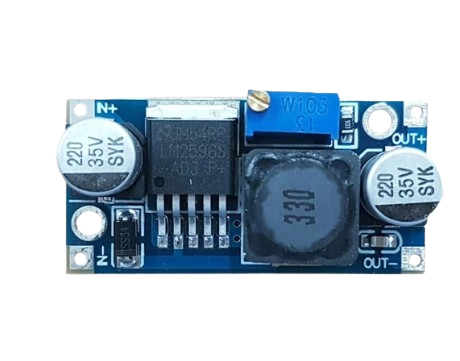
A DC-DC buck converter is a type of power converter that steps down voltage from a higher level to a lower level while maintaining efficiency. It uses a switching element, an inductor, and a diode to convert the input voltage to a lower output voltage. This component is widely used in applications where efficient voltage regulation is required, such as powering microcontrollers, LEDs, and other low-voltage devices from higher-voltage sources like batteries or power supplies.
Explore Projects Built with DC-DC buck converter


Explore Projects Built with DC-DC buck converter
Common Applications and Use Cases
- Powering microcontrollers (e.g., Arduino, Raspberry Pi) from higher voltage sources.
- Voltage regulation in battery-powered devices.
- LED drivers for low-voltage lighting systems.
- Industrial and automotive electronics.
- Portable devices requiring efficient power management.
Technical Specifications
Key Technical Details
- Input Voltage Range: Typically 4.5V to 40V (varies by model).
- Output Voltage Range: Adjustable, typically 1.25V to 35V.
- Output Current: Up to 3A (depending on the model and heat dissipation).
- Efficiency: Up to 90% or higher.
- Switching Frequency: Typically 150 kHz to 1 MHz.
- Operating Temperature: -40°C to +85°C (varies by model).
Pin Configuration and Descriptions
Below is a typical pin configuration for a DC-DC buck converter module:
| Pin Name | Description |
|---|---|
| VIN | Input voltage pin. Connect the higher voltage source here. |
| GND | Ground pin. Connect to the ground of the circuit. |
| VOUT | Output voltage pin. Provides the stepped-down voltage to the load. |
| EN (optional) | Enable pin. Used to turn the converter on or off (active high). |
| ADJ (optional) | Adjustment pin. Used to set the output voltage (via a potentiometer or resistor). |
Note: Some modules may have additional pins or features, such as a feedback pin or a power-good indicator. Always refer to the specific datasheet for your module.
Usage Instructions
How to Use the Component in a Circuit
- Connect the Input Voltage:
- Connect the positive terminal of your power source to the
VINpin. - Connect the negative terminal of your power source to the
GNDpin.
- Connect the positive terminal of your power source to the
- Set the Output Voltage:
- If the module has an adjustable output, use the onboard potentiometer to set the desired output voltage.
- Measure the output voltage at the
VOUTpin using a multimeter while adjusting the potentiometer.
- Connect the Load:
- Connect the positive terminal of your load to the
VOUTpin. - Connect the negative terminal of your load to the
GNDpin.
- Connect the positive terminal of your load to the
- Enable the Converter (if applicable):
- If the module has an
ENpin, ensure it is connected to a high logic level (e.g., 3.3V or 5V) to enable the converter.
- If the module has an
Important Considerations and Best Practices
- Input Voltage: Ensure the input voltage is within the specified range of the module. Exceeding the maximum input voltage can damage the converter.
- Heat Dissipation: For high current loads, the module may generate heat. Use a heatsink or active cooling if necessary.
- Output Voltage Ripple: Add a capacitor at the output to reduce voltage ripple if your application is sensitive to noise.
- Current Limitation: Do not exceed the maximum output current rating of the module to avoid overheating or damage.
- Polarity: Double-check the polarity of your connections to avoid damaging the module.
Example: Using a DC-DC Buck Converter with Arduino UNO
Below is an example of how to use a DC-DC buck converter to power an Arduino UNO from a 12V power source:
- Connect the 12V power source to the
VINandGNDpins of the buck converter. - Adjust the output voltage of the buck converter to 5V using the onboard potentiometer.
- Connect the
VOUTpin of the buck converter to the5Vpin of the Arduino UNO. - Connect the
GNDpin of the buck converter to theGNDpin of the Arduino UNO.
Here is a simple Arduino sketch to test the setup:
// This sketch blinks the onboard LED of the Arduino UNO
// Ensure the Arduino is powered via the buck converter at 5V

void setup() {
  pinMode(LED_BUILTIN, OUTPUT); // Set the onboard LED pin as output
}

void loop() {
  digitalWrite(LED_BUILTIN, HIGH); // Turn the LED on
  delay(1000);                     // Wait for 1 second
  digitalWrite(LED_BUILTIN, LOW);  // Turn the LED off
  delay(1000);                     // Wait for 1 second
}
Troubleshooting and FAQs
Common Issues and Solutions
| Issue | Possible Cause | Solution |
|---|---|---|
| No output voltage | Incorrect wiring or polarity | Double-check all connections and ensure correct polarity. |
| Output voltage is unstable | Insufficient input voltage or high load current | Ensure the input voltage is stable and within the specified range. |
| Module overheats | Exceeding current rating or poor heat dissipation | Reduce the load current or add a heatsink to the module. |
| Cannot adjust output voltage | Faulty potentiometer or incorrect adjustment procedure | Replace the potentiometer or follow the adjustment steps carefully. |
| High output voltage ripple | Insufficient output filtering | Add a low ESR capacitor (e.g., 100µF) at the output to reduce ripple. |
FAQs
Can I use a DC-DC buck converter to power sensitive electronics?
- Yes, but ensure the output voltage ripple is minimized by adding appropriate filtering capacitors.
What happens if I exceed the input voltage range?
- Exceeding the input voltage range can permanently damage the module. Always stay within the specified range.
Can I use the buck converter to step up voltage?
- No, a buck converter is designed only to step down voltage. For stepping up voltage, use a boost converter.
How do I calculate the required input current?
- Use the formula:
Input Current = (Output Power / Input Voltage) / Efficiency. Ensure your power source can supply this current.
- Use the formula:
By following this documentation, you can effectively use a DC-DC buck converter in your projects while avoiding common pitfalls.