Cirkit Designer Logo
Cirkit Designer
Your all-in-one circuit design IDE
Home / 
Component Documentation

How to Use Round Rocker Switch: Examples, Pinouts, and Specs

Image of Round Rocker Switch
Cirkit Designer LogoDesign with Round Rocker Switch in Cirkit Designer

Introduction

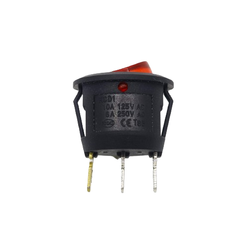
A Round Rocker Switch is a simple yet essential electrical component used to control the flow of electricity within a circuit. It is characterized by its circular form factor and a rocker mechanism that allows users to switch between an "ON" and "OFF" state, thereby enabling or disabling the flow of current. These switches are commonly found in various applications, including household appliances, office equipment, automotive, and industrial machinery.

Explore Projects Built with Round Rocker Switch

Use Cirkit Designer to design, explore, and prototype these projects online. Some projects support real-time simulation. Click "Open Project" to start designing instantly!
SPST Rocker Switch Array Circuit
Image of SWITCH CONNECTION: A project utilizing Round Rocker Switch in a practical application
This circuit features a parallel arrangement of SPST rocker switches, each capable of independently controlling the connection of a separate circuit branch to a common line. It is likely designed for simple on/off control of multiple individual loads or signals, with each switch operating a distinct load or signal path.
Cirkit Designer LogoOpen Project in Cirkit Designer
220V AC Bulb Circuit with Rocker Switch Control
Image of Lampu Kuning: A project utilizing Round Rocker Switch in a practical application
This circuit is designed to control the power to an AC bulb using a rocker switch. The power 220v source is connected through the rocker switch to the bulb, allowing the user to turn the light on and off. There is no microcontroller or complex logic involved; it's a simple manual switching circuit.
Cirkit Designer LogoOpen Project in Cirkit Designer
ESP32-Controlled Lighting and Ventilation System
Image of ECE STAFFROOM AUTOMATION: A project utilizing Round Rocker Switch in a practical application
This circuit is designed to control multiple AC-powered devices, such as LED bulbs and fans, using an ESP32 microcontroller and an 8-channel relay module. The ESP32's GPIO pins are connected to the relay inputs, allowing it to switch the relays on and off, which in turn controls the power to the connected devices. Rocker switches are used to provide manual control over the GPIO pins, and a 5V adapter powers the ESP32 and the relay module.
Cirkit Designer LogoOpen Project in Cirkit Designer
Battery-Powered Gear Motor Control with Rocker Switch
Image of Dish Washer: A project utilizing Round Rocker Switch in a practical application
This circuit is a simple control circuit for a gear motor, powered by a 9V battery. The rocker switch is used to turn the motor on and off by completing or breaking the circuit between the battery and the motor. There is no microcontroller or complex logic involved, making it a straightforward power control circuit.
Cirkit Designer LogoOpen Project in Cirkit Designer

Explore Projects Built with Round Rocker Switch

Use Cirkit Designer to design, explore, and prototype these projects online. Some projects support real-time simulation. Click "Open Project" to start designing instantly!
Image of SWITCH CONNECTION: A project utilizing Round Rocker Switch in a practical application
SPST Rocker Switch Array Circuit
This circuit features a parallel arrangement of SPST rocker switches, each capable of independently controlling the connection of a separate circuit branch to a common line. It is likely designed for simple on/off control of multiple individual loads or signals, with each switch operating a distinct load or signal path.
Cirkit Designer LogoOpen Project in Cirkit Designer
Image of Lampu Kuning: A project utilizing Round Rocker Switch in a practical application
220V AC Bulb Circuit with Rocker Switch Control
This circuit is designed to control the power to an AC bulb using a rocker switch. The power 220v source is connected through the rocker switch to the bulb, allowing the user to turn the light on and off. There is no microcontroller or complex logic involved; it's a simple manual switching circuit.
Cirkit Designer LogoOpen Project in Cirkit Designer
Image of ECE STAFFROOM AUTOMATION: A project utilizing Round Rocker Switch in a practical application
ESP32-Controlled Lighting and Ventilation System
This circuit is designed to control multiple AC-powered devices, such as LED bulbs and fans, using an ESP32 microcontroller and an 8-channel relay module. The ESP32's GPIO pins are connected to the relay inputs, allowing it to switch the relays on and off, which in turn controls the power to the connected devices. Rocker switches are used to provide manual control over the GPIO pins, and a 5V adapter powers the ESP32 and the relay module.
Cirkit Designer LogoOpen Project in Cirkit Designer
Image of Dish Washer: A project utilizing Round Rocker Switch in a practical application
Battery-Powered Gear Motor Control with Rocker Switch
This circuit is a simple control circuit for a gear motor, powered by a 9V battery. The rocker switch is used to turn the motor on and off by completing or breaking the circuit between the battery and the motor. There is no microcontroller or complex logic involved, making it a straightforward power control circuit.
Cirkit Designer LogoOpen Project in Cirkit Designer

Common Applications and Use Cases

  • Power control for electronic devices
  • Lighting fixtures
  • Automotive dashboards
  • Industrial control panels

Technical Specifications

Key Technical Details

  • Voltage Rating: Typically ranges from 110V to 250V AC
  • Current Rating: Commonly rated for 3A to 20A
  • Contact Configuration: SPST (Single Pole, Single Throw) or SPDT (Single Pole, Double Throw)
  • Terminal Type: Solder lug, quick connect, or PCB mount
  • Switching Mechanism: Rocker
  • Material: Plastic, metal, or a combination
  • Color: Various colors available, often with an illuminated option

Pin Configuration and Descriptions

Pin Number Description Notes
1 Input (Power Supply) Connect to the live wire (L)
2 Output (Load) Connect to the device or load
3 Ground (Optional) For illuminated switches

Note: The pin configuration may vary depending on the specific model and manufacturer.

Usage Instructions

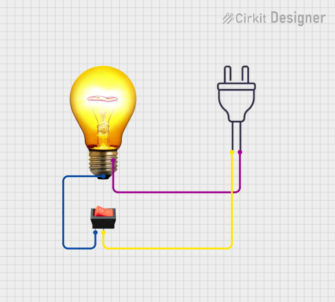
How to Use the Component in a Circuit

  1. Power Off: Ensure that the power supply to the circuit is turned off before installing the switch.
  2. Wiring: Connect the live wire from the power supply to pin 1 of the switch. Connect pin 2 to the load that the switch will control.
  3. Mounting: Secure the switch in place, typically by snapping it into a pre-cut panel hole.
  4. Testing: Once installed, turn on the power supply and test the switch operation.

Important Considerations and Best Practices

  • Load Rating: Do not exceed the voltage and current ratings of the switch to prevent damage.
  • Wiring: Ensure secure and correct wiring to prevent short circuits.
  • Mounting: Verify that the size of the panel cut-out matches the switch dimensions.
  • Illumination: If using an illuminated switch, ensure the ground pin is properly connected.

Troubleshooting and FAQs

Common Issues

  • Switch Does Not Operate: Check for loose connections or a blown fuse.
  • Illumination Not Working: Verify that the ground wire is connected if using an illuminated switch.

Solutions and Tips for Troubleshooting

  • Loose Connections: Tighten connections and ensure wires are properly soldered or crimped.
  • Blown Fuse: Replace the fuse and check for any circuit overloads.

FAQs

Q: Can I use this switch with a DC power supply? A: Yes, but ensure the DC voltage and current do not exceed the switch's ratings.

Q: How do I know if the switch is in the ON position? A: Some switches have an indicator line or illumination to show the ON position.

Q: Is it possible to replace the switch in an existing device? A: Yes, as long as the replacement switch has compatible ratings and dimensions.

Example Code for Arduino UNO Connection

// Example code to control an LED using a Round Rocker Switch connected to an Arduino UNO

const int switchPin = 2; // Connect the output pin of the switch to digital pin 2
const int ledPin = 13;   // Built-in LED on Arduino UNO

void setup() {
  pinMode(ledPin, OUTPUT);      // Set the LED pin as an output
  pinMode(switchPin, INPUT);    // Set the switch pin as an input
}

void loop() {
  int switchState = digitalRead(switchPin); // Read the state of the switch
  if (switchState == HIGH) {
    digitalWrite(ledPin, HIGH); // Turn on the LED if the switch is in the ON position
  } else {
    digitalWrite(ledPin, LOW);  // Turn off the LED if the switch is in the OFF position
  }
}

Note: The above code assumes that the switch is wired to provide a HIGH signal to the Arduino when in the ON position. Adjust the code accordingly if your switch configuration is different.

This documentation provides a comprehensive guide to using a Round Rocker Switch. For specific models or additional technical support, please refer to the manufacturer's datasheet or contact their customer service.