Cirkit Designer Logo
Cirkit Designer
Your all-in-one circuit design IDE
Home / 
Component Documentation

How to Use AMS1117: Examples, Pinouts, and Specs

Image of AMS1117
Cirkit Designer LogoDesign with AMS1117 in Cirkit Designer

Introduction

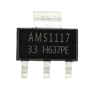
The AMS1117 is a low dropout (LDO) voltage regulator designed to provide a stable and regulated output voltage with a maximum output current of 1A. Manufactured by ESP8266 under the part ID NODMCU, this component is widely used in power supply circuits to step down and regulate voltage levels for microcontrollers, sensors, and other electronic devices. Its compact design and reliable performance make it a popular choice for both hobbyist and professional applications.

Explore Projects Built with AMS1117

Use Cirkit Designer to design, explore, and prototype these projects online. Some projects support real-time simulation. Click "Open Project" to start designing instantly!
ESP32-Powered Wi-Fi Enabled Microcontroller Circuit with AMS1117 Voltage Regulation
Image of Power regualator: A project utilizing AMS1117 in a practical application
This circuit features an ESP32 microcontroller powered by a 3.3V AMS1117 voltage regulator. The power is supplied through a 2.1mm DC barrel jack, which provides the input voltage to the AMS1117, and the regulated 3.3V output is connected to the ESP32's VIN pin. The ground connections are shared among the ESP32 and the voltage regulator.
Cirkit Designer LogoOpen Project in Cirkit Designer
Teensy 4.1-Based Multi-Channel Potentiometer Interface with 74HC4051 Mux and AMS1117 3.3V Regulator
Image of redrum: A project utilizing AMS1117 in a practical application
This circuit features a Teensy 4.1 microcontroller interfaced with a SparkFun 74HC4051 8-channel multiplexer to read multiple rotary potentiometers. The AMS1117 3.3V voltage regulator provides a stable 3.3V supply to the multiplexer and potentiometers, while electrolytic and ceramic capacitors are used for power supply filtering and stabilization.
Cirkit Designer LogoOpen Project in Cirkit Designer
Wemos S2 Mini Controlled Smart Device with OLED Display, Thermal Printing, and RGB LED Strip
Image of DT NEA - Noah Patel: A project utilizing AMS1117 in a practical application
This circuit features a Wemos S2 Mini microcontroller that controls a WS2812 RGB LED strip and communicates with a 0.96" OLED display and a 58mm mini thermal printer. The ACS712 Current Sensor is interfaced with the microcontroller to monitor current, and power is managed by a CD42 BMS connected to two 18650 Li-ion batteries, with a USB-C PD Trigger Board for power delivery. The circuit is designed for visual output (LED strip, OLED display), printing capabilities, and current sensing, likely for a portable, battery-powered monitoring and display device.
Cirkit Designer LogoOpen Project in Cirkit Designer
Smart Weighing System with ESP8266 and HX711 - Battery Powered and Wi-Fi Enabled
Image of gggg: A project utilizing AMS1117 in a practical application
This circuit is a multi-sensor data acquisition system powered by a 18650 battery and managed by an ESP8266 microcontroller. It includes a load sensor interfaced with an HX711 module for weight measurement, an IR sensor, an ADXL345 accelerometer, a VL53L0X distance sensor, and a Neo 6M GPS module for location tracking. The system is designed for wireless data transmission and is supported by a TP4056 module for battery charging.
Cirkit Designer LogoOpen Project in Cirkit Designer

Explore Projects Built with AMS1117

Use Cirkit Designer to design, explore, and prototype these projects online. Some projects support real-time simulation. Click "Open Project" to start designing instantly!
Image of Power regualator: A project utilizing AMS1117 in a practical application
ESP32-Powered Wi-Fi Enabled Microcontroller Circuit with AMS1117 Voltage Regulation
This circuit features an ESP32 microcontroller powered by a 3.3V AMS1117 voltage regulator. The power is supplied through a 2.1mm DC barrel jack, which provides the input voltage to the AMS1117, and the regulated 3.3V output is connected to the ESP32's VIN pin. The ground connections are shared among the ESP32 and the voltage regulator.
Cirkit Designer LogoOpen Project in Cirkit Designer
Image of redrum: A project utilizing AMS1117 in a practical application
Teensy 4.1-Based Multi-Channel Potentiometer Interface with 74HC4051 Mux and AMS1117 3.3V Regulator
This circuit features a Teensy 4.1 microcontroller interfaced with a SparkFun 74HC4051 8-channel multiplexer to read multiple rotary potentiometers. The AMS1117 3.3V voltage regulator provides a stable 3.3V supply to the multiplexer and potentiometers, while electrolytic and ceramic capacitors are used for power supply filtering and stabilization.
Cirkit Designer LogoOpen Project in Cirkit Designer
Image of DT NEA - Noah Patel: A project utilizing AMS1117 in a practical application
Wemos S2 Mini Controlled Smart Device with OLED Display, Thermal Printing, and RGB LED Strip
This circuit features a Wemos S2 Mini microcontroller that controls a WS2812 RGB LED strip and communicates with a 0.96" OLED display and a 58mm mini thermal printer. The ACS712 Current Sensor is interfaced with the microcontroller to monitor current, and power is managed by a CD42 BMS connected to two 18650 Li-ion batteries, with a USB-C PD Trigger Board for power delivery. The circuit is designed for visual output (LED strip, OLED display), printing capabilities, and current sensing, likely for a portable, battery-powered monitoring and display device.
Cirkit Designer LogoOpen Project in Cirkit Designer
Image of gggg: A project utilizing AMS1117 in a practical application
Smart Weighing System with ESP8266 and HX711 - Battery Powered and Wi-Fi Enabled
This circuit is a multi-sensor data acquisition system powered by a 18650 battery and managed by an ESP8266 microcontroller. It includes a load sensor interfaced with an HX711 module for weight measurement, an IR sensor, an ADXL345 accelerometer, a VL53L0X distance sensor, and a Neo 6M GPS module for location tracking. The system is designed for wireless data transmission and is supported by a TP4056 module for battery charging.
Cirkit Designer LogoOpen Project in Cirkit Designer

Common Applications and Use Cases

  • Voltage regulation for microcontrollers (e.g., ESP8266, Arduino, Raspberry Pi)
  • Powering sensors and modules in embedded systems
  • Battery-powered devices requiring stable voltage
  • General-purpose voltage regulation in DIY electronics projects

Technical Specifications

The AMS1117 is available in various fixed output voltage versions (e.g., 1.2V, 1.5V, 1.8V, 2.5V, 3.3V, 5.0V) as well as an adjustable version. Below are the key technical details:

Parameter Value
Input Voltage Range 4.6V to 15V
Output Voltage Options 1.2V, 1.5V, 1.8V, 2.5V, 3.3V, 5.0V
Maximum Output Current 1A
Dropout Voltage 1.1V (at 1A load)
Operating Temperature 0°C to 125°C
Package Type SOT-223, TO-252

Pin Configuration and Descriptions

The AMS1117 has three pins, as shown in the table below:

Pin Number Pin Name Description
1 GND Ground pin (connect to circuit ground)
2 VOUT Regulated output voltage
3 VIN Input voltage (connect to unregulated power)

Usage Instructions

How to Use the AMS1117 in a Circuit

  1. Input Voltage: Connect the unregulated input voltage (4.6V to 15V) to the VIN pin. Ensure the input voltage is at least 1.1V higher than the desired output voltage to maintain proper regulation.
  2. Output Voltage: Connect the load to the VOUT pin. The output voltage will be regulated to the specified value (e.g., 3.3V for the AMS1117-3.3).
  3. Ground Connection: Connect the GND pin to the circuit ground.
  4. Capacitors: Add decoupling capacitors for stability:
    • A 10µF capacitor on the input side (VIN to GND).
    • A 10µF capacitor on the output side (VOUT to GND).

Important Considerations and Best Practices

  • Heat Dissipation: The AMS1117 can dissipate heat during operation, especially at higher currents. Use a heatsink or ensure proper ventilation if the regulator gets too hot.
  • Input Voltage Range: Do not exceed the maximum input voltage of 15V to avoid damaging the component.
  • Load Current: Ensure the load current does not exceed 1A to prevent overheating or failure.
  • Bypass Capacitors: Always use the recommended capacitors to ensure stable operation and minimize noise.

Example: Using AMS1117-3.3 with Arduino UNO

The AMS1117-3.3 can be used to power an Arduino UNO or other 3.3V devices. Below is an example circuit and Arduino code to demonstrate its usage:

Circuit Diagram

  1. Connect a 9V battery or DC power supply to the VIN pin.
  2. Connect the VOUT pin to the 3.3V input of the Arduino UNO.
  3. Connect the GND pin to the ground of the Arduino UNO.

Arduino Code Example

// Example code to read an analog sensor powered by AMS1117-3.3
// The sensor is connected to pin A0 of the Arduino UNO.

const int sensorPin = A0;  // Analog pin connected to the sensor
int sensorValue = 0;       // Variable to store the sensor reading

void setup() {
  Serial.begin(9600);  // Initialize serial communication at 9600 baud
}

void loop() {
  sensorValue = analogRead(sensorPin);  // Read the sensor value
  Serial.print("Sensor Value: ");
  Serial.println(sensorValue);         // Print the sensor value to the Serial Monitor
  delay(1000);                          // Wait for 1 second before the next reading
}

Troubleshooting and FAQs

Common Issues and Solutions

  1. No Output Voltage:

    • Check the input voltage. Ensure it is within the specified range (4.6V to 15V).
    • Verify the connections to the VIN, VOUT, and GND pins.
    • Ensure the load current does not exceed 1A.
  2. Overheating:

    • Check if the input voltage is too high or the load current is excessive.
    • Use a heatsink or improve ventilation to dissipate heat.
  3. Unstable Output Voltage:

    • Ensure the recommended capacitors (10µF) are connected to the input and output pins.
    • Check for loose or poor connections in the circuit.

FAQs

Q: Can I use the AMS1117 to power a 5V device?
A: Yes, you can use the AMS1117-5.0 version to provide a regulated 5V output. Ensure the input voltage is at least 6.1V (5V + 1.1V dropout voltage).

Q: What happens if the input voltage drops below the required level?
A: If the input voltage is less than the required dropout voltage, the AMS1117 will not regulate properly, and the output voltage may drop below the specified value.

Q: Can I use the AMS1117 without capacitors?
A: It is not recommended. The capacitors are essential for stable operation and to minimize noise in the output voltage.

Q: Is the AMS1117 suitable for battery-powered applications?
A: Yes, but ensure the input voltage remains within the specified range and consider the dropout voltage when designing the circuit.