
How to Use 1N4001 Rectifier Diode (300 mil): Examples, Pinouts, and Specs

 Design with 1N4001 Rectifier Diode (300 mil) in Cirkit Designer
Introduction
The 1N4001 is a general-purpose silicon rectifier diode designed for low-frequency rectification applications. It is capable of handling a maximum reverse voltage of 50V and a forward current of up to 1A. This diode is widely used in power supply circuits to convert alternating current (AC) to direct current (DC). Its robust design and reliability make it a popular choice for hobbyists and professionals alike.
Explore Projects Built with 1N4001 Rectifier Diode (300 mil)
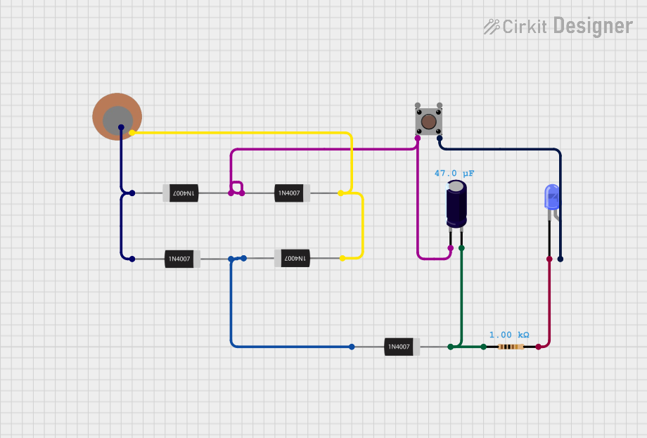 Open Project in Cirkit Designer
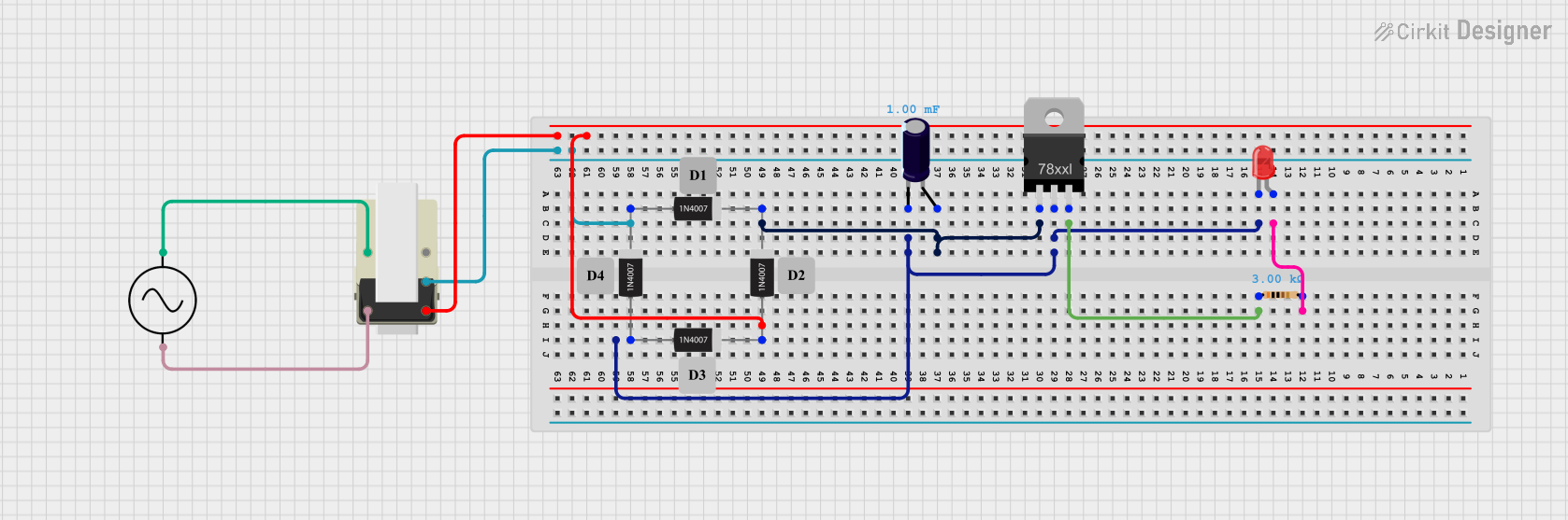 Open Project in Cirkit Designer
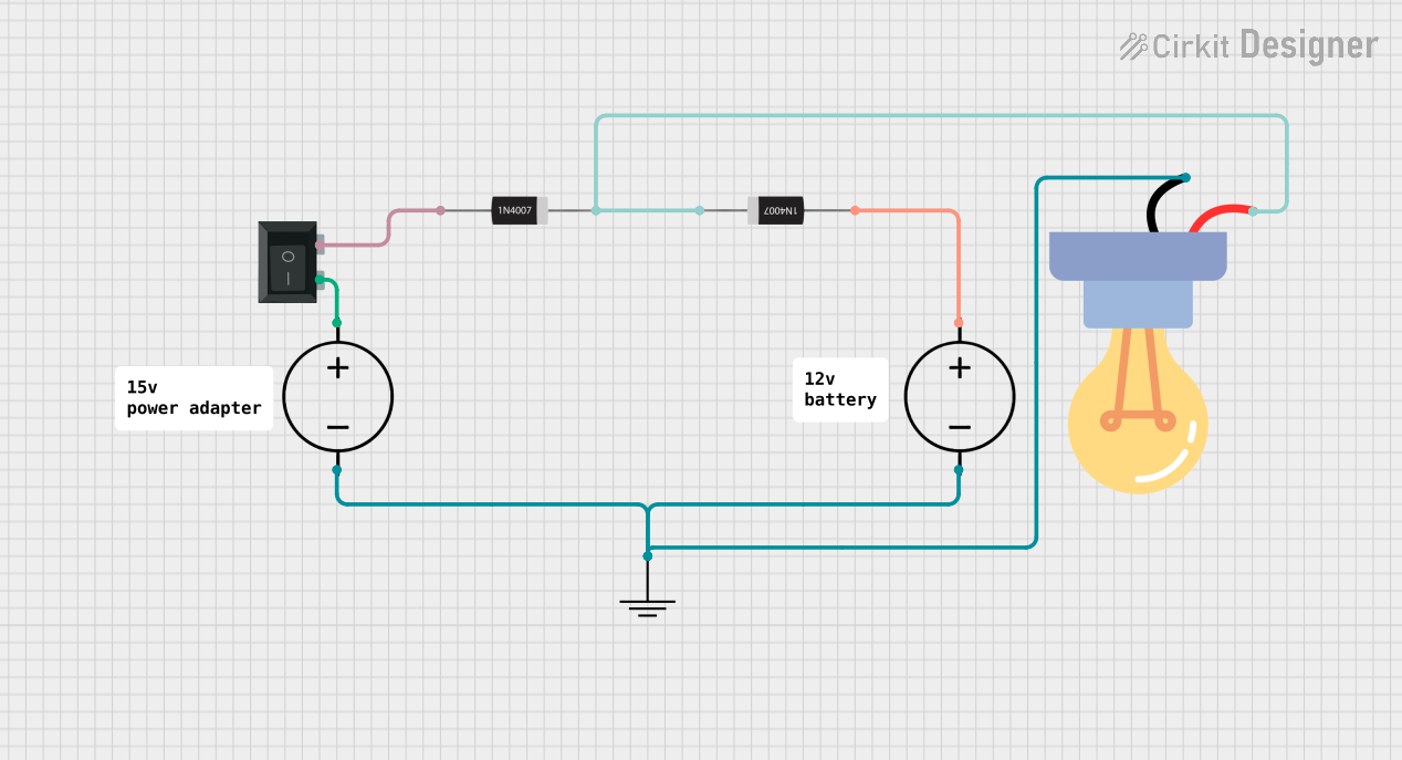 Open Project in Cirkit Designer
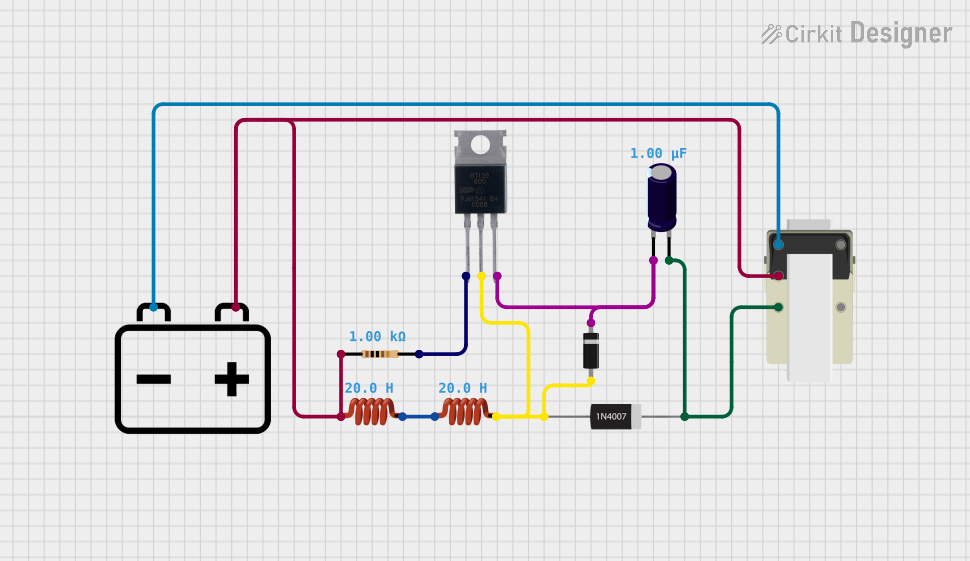 Open Project in Cirkit Designer
Explore Projects Built with 1N4001 Rectifier Diode (300 mil)
Open Project in Cirkit DesignerOpen Project in Cirkit DesignerOpen Project in Cirkit DesignerOpen Project in Cirkit DesignerCommon Applications
- AC to DC rectification in power supplies
- Protection against reverse polarity in circuits
- Voltage clamping and freewheeling in inductive loads
- General-purpose low-frequency rectification
Technical Specifications
The following table outlines the key technical specifications of the 1N4001 rectifier diode:
| Parameter | Value |
|---|---|
| Maximum Reverse Voltage | 50V |
| Maximum Forward Current | 1A |
| Peak Surge Current | 30A (8.3ms single half-sine) |
| Forward Voltage Drop | 0.7V (typical at 1A) |
| Reverse Current | 5µA (at 25°C) |
| Operating Temperature | -65°C to +150°C |
| Package Type | DO-41 (300 mil) |
Pin Configuration
The 1N4001 diode has two terminals:
| Pin | Description |
|---|---|
| Anode | Positive terminal (current enters) |
| Cathode | Negative terminal (current exits) |
The cathode is marked with a silver or white band on the diode body.
Usage Instructions
How to Use the 1N4001 in a Circuit
- Identify the Terminals: Locate the cathode (marked with a silver/white band) and the anode.
- Connect in the Correct Orientation:
- For rectification, connect the anode to the positive side of the AC signal and the cathode to the load or DC output.
- For reverse polarity protection, connect the cathode to the positive terminal of the power supply and the anode to the circuit.
- Add Supporting Components: In rectifier circuits, use capacitors to smooth the DC output and resistors if necessary to limit current.
- Verify Ratings: Ensure the voltage and current in your circuit do not exceed the diode's maximum ratings (50V reverse voltage, 1A forward current).
Example: Full-Wave Rectifier Circuit
The 1N4001 can be used in a bridge rectifier configuration to convert AC to DC. Below is an example of how to connect four 1N4001 diodes in a full-wave rectifier circuit:
       ~ AC Input ~
         |       |
        ---     ---
       |   |   |   |
       | D1|---|D2 |
       |   |   |   |
        ---     ---
         |       |
         |       |
        ---     ---  Load
       |   |   |   |
       | D3|---|D4 |
       |   |   |   |
        ---     ---
         |       |
         |       |
        ---     ---
Using the 1N4001 with Arduino UNO
The 1N4001 can be used to protect an Arduino UNO from reverse polarity. Below is an example circuit and code:
Circuit
- Connect the cathode of the 1N4001 to the Arduino's VIN pin.
- Connect the anode to the positive terminal of the power supply.
- Connect the negative terminal of the power supply to the Arduino's GND pin.
Code Example
// Simple Arduino code to blink an LED
// Ensure the 1N4001 diode is protecting the Arduino from reverse polarity

const int ledPin = 13; // Built-in LED pin on Arduino UNO

void setup() {
  pinMode(ledPin, OUTPUT); // Set LED pin as output
}

void loop() {
  digitalWrite(ledPin, HIGH); // Turn LED on
  delay(1000);               // Wait for 1 second
  digitalWrite(ledPin, LOW);  // Turn LED off
  delay(1000);               // Wait for 1 second
}
Best Practices
- Always check the diode's orientation before powering the circuit.
- Use a heat sink or ensure proper ventilation if the diode is operating near its maximum current rating.
- Avoid exceeding the diode's voltage and current ratings to prevent damage.
Troubleshooting and FAQs
Common Issues
Diode Overheating:
- Cause: Exceeding the maximum forward current or reverse voltage.
- Solution: Ensure the circuit operates within the diode's rated specifications.
No Output Voltage in Rectifier Circuit:
- Cause: Incorrect diode orientation.
- Solution: Verify the anode and cathode connections.
High Reverse Leakage Current:
- Cause: Operating the diode at high temperatures.
- Solution: Ensure adequate cooling and operate within the specified temperature range.
Voltage Drop Too High:
- Cause: Forward current is too high.
- Solution: Use a diode with a lower forward voltage drop if necessary.
FAQs
Q1: Can I use the 1N4001 for high-frequency rectification?
A1: No, the 1N4001 is designed for low-frequency applications (e.g., 50Hz or 60Hz). For high-frequency rectification, consider using a Schottky diode.
Q2: What happens if I exceed the maximum reverse voltage?
A2: Exceeding the reverse voltage can cause the diode to break down and fail permanently.
Q3: Can I use the 1N4001 in parallel with another diode to increase current capacity?
A3: While it is possible, it is not recommended due to uneven current sharing between the diodes. Use a single diode with a higher current rating instead.
Q4: How do I identify the cathode if the marking is unclear?
A4: Use a multimeter in diode mode. The cathode is the terminal connected to the negative probe when the multimeter shows a forward voltage drop (~0.7V).