How to Use 1.8" 128x160 TFT 65K color screen: Examples, Pinouts, and Specs
Introduction
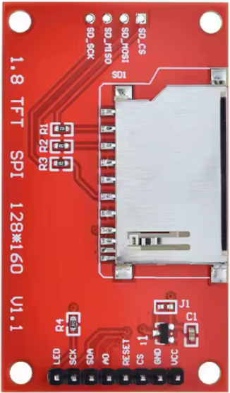
The 1.8" 128x160 TFT 65K Color Screen (Manufacturer Part ID: MSP1803) is a compact, high-resolution display module designed for use in embedded systems and portable devices. It features a resolution of 128x160 pixels and supports up to 65,000 colors, making it ideal for applications requiring vibrant and detailed graphical output. The module is powered by the ST7735S driver, which provides efficient control and communication with microcontrollers.
Explore Projects Built with 1.8" 128x160 TFT 65K color screen


Explore Projects Built with 1.8" 128x160 TFT 65K color screen
Common Applications
- Wearable devices
- Portable gaming consoles
- IoT dashboards and displays
- Small-scale graphical user interfaces (GUIs)
- Educational and hobbyist projects
Technical Specifications
Key Technical Details
| Parameter | Value |
|---|---|
| Display Type | TFT LCD |
| Resolution | 128x160 pixels |
| Color Depth | 65K colors (16-bit RGB) |
| Driver IC | ST7735S |
| Operating Voltage | 3.3V (logic) |
| Backlight Voltage | 3.0V to 3.3V |
| Communication Protocol | SPI (Serial Peripheral Interface) |
| Dimensions | 1.8 inches (diagonal) |
| Operating Temperature | -20°C to 70°C |
Pin Configuration and Descriptions
The module typically has an 8-pin interface. Below is the pinout and description:
| Pin Number | Pin Name | Description |
|---|---|---|
| 1 | GND | Ground connection |
| 2 | VCC | Power supply (3.3V) |
| 3 | SCL | Serial Clock Line (SPI clock input) |
| 4 | SDA | Serial Data Line (SPI data input/output) |
| 5 | RES | Reset pin (active low) |
| 6 | DC | Data/Command control pin (High = Data, Low = Command) |
| 7 | CS | Chip Select (active low) |
| 8 | BLK | Backlight control (connect to 3.3V for always-on backlight or PWM for dimming) |
Usage Instructions
How to Use the Component in a Circuit
- Power Supply: Connect the VCC pin to a 3.3V power source and the GND pin to ground.
- SPI Communication: Connect the SCL (clock) and SDA (data) pins to the corresponding SPI pins on your microcontroller.
- Control Pins:
- Connect the CS pin to a GPIO pin on your microcontroller to enable/disable the display.
- Use the DC pin to toggle between sending data or commands.
- Connect the RES pin to a GPIO pin for resetting the display.
- Backlight: Connect the BLK pin to 3.3V for constant backlight or to a PWM pin for adjustable brightness.
Important Considerations and Best Practices
- Voltage Levels: Ensure all logic signals are at 3.3V. If using a 5V microcontroller (e.g., Arduino UNO), use a level shifter to avoid damaging the display.
- SPI Speed: The ST7735S driver supports SPI speeds up to 15 MHz. Use a lower speed if communication errors occur.
- Initialization: The display requires specific initialization commands to configure the ST7735S driver. Use a compatible library (e.g., Adafruit GFX) to simplify this process.
- Backlight Control: For energy efficiency, use PWM to control the backlight brightness.
Example Code for Arduino UNO
Below is an example of how to use the display with an Arduino UNO using the Adafruit GFX and Adafruit ST7735 libraries:
#include <Adafruit_GFX.h>      // Core graphics library
#include <Adafruit_ST7735.h>   // Hardware-specific library for ST7735

// Define pins for the display
#define TFT_CS     10  // Chip Select pin
#define TFT_RST    9   // Reset pin
#define TFT_DC     8   // Data/Command pin

// Initialize the display object
Adafruit_ST7735 tft = Adafruit_ST7735(TFT_CS, TFT_DC, TFT_RST);

void setup() {
  // Initialize the display
  tft.initR(INITR_BLACKTAB);  // Use the Black Tab configuration
  tft.fillScreen(ST77XX_BLACK);  // Clear the screen with black color

  // Display a message
  tft.setTextColor(ST77XX_WHITE);  // Set text color to white
  tft.setTextSize(1);              // Set text size
  tft.setCursor(0, 0);             // Set cursor position
  tft.println("Hello, World!");    // Print text to the screen
}

void loop() {
  // Add your code here
}
Notes:
- Install the Adafruit GFX and Adafruit ST7735 libraries via the Arduino Library Manager.
- Ensure the SPI pins on the Arduino UNO (MOSI, SCK) are connected to the SDA and SCL pins of the display, respectively.
Troubleshooting and FAQs
Common Issues and Solutions
Display Not Turning On
- Cause: Incorrect power supply or loose connections.
- Solution: Verify that the VCC pin is connected to a 3.3V source and all connections are secure.
No Image or Distorted Output
- Cause: Incorrect initialization or SPI communication issues.
- Solution: Ensure the correct initialization sequence is used. Use a library like Adafruit ST7735 to simplify setup.
Backlight Not Working
- Cause: BLK pin not connected or insufficient voltage.
- Solution: Connect the BLK pin to 3.3V or a PWM pin for brightness control.
Flickering or Artifacts
- Cause: SPI speed too high or poor wiring.
- Solution: Reduce the SPI clock speed and use shorter, high-quality wires.
FAQs
Q: Can I use this display with a 5V microcontroller?
A: Yes, but you must use a level shifter to convert 5V logic signals to 3.3V to avoid damaging the display.
Q: What is the maximum SPI clock speed supported?
A: The ST7735S driver supports SPI speeds up to 15 MHz. Use lower speeds if you encounter communication issues.
Q: Can I control the backlight brightness?
A: Yes, connect the BLK pin to a PWM-capable pin on your microcontroller to adjust brightness.
Q: Is this display compatible with Raspberry Pi?
A: Yes, the display can be used with Raspberry Pi via SPI, but you may need to modify the configuration files for proper operation.