
How to Use PICAXE-40X2: Examples, Pinouts, and Specs

 Design with PICAXE-40X2 in Cirkit Designer
Introduction
The PICAXE-40X2, manufactured by Revolution Education Ltd, is a versatile microcontroller designed for educational, hobbyist, and prototyping applications. With its 40-pin configuration, it provides ample input/output (I/O) options for controlling sensors, actuators, and other electronic devices. The PICAXE-40X2 is programmed using a simple BASIC-like language, making it accessible to beginners while still offering advanced features for experienced users.
Explore Projects Built with PICAXE-40X2
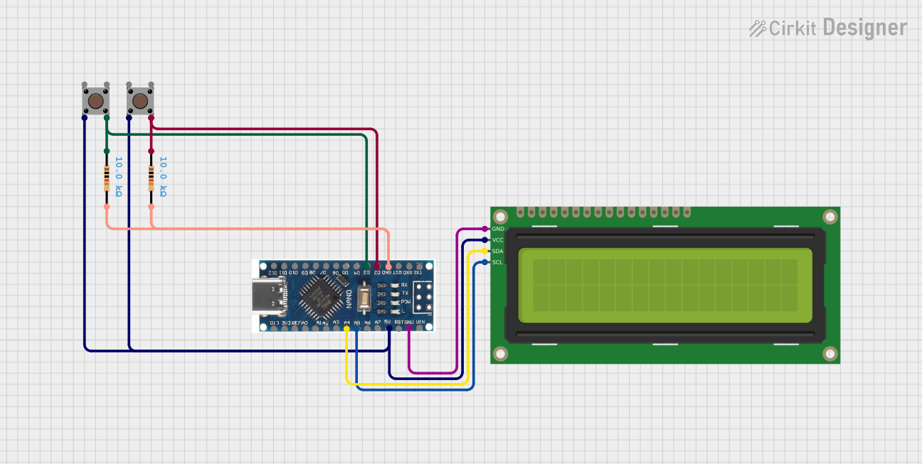 Open Project in Cirkit Designer
 Open Project in Cirkit Designer
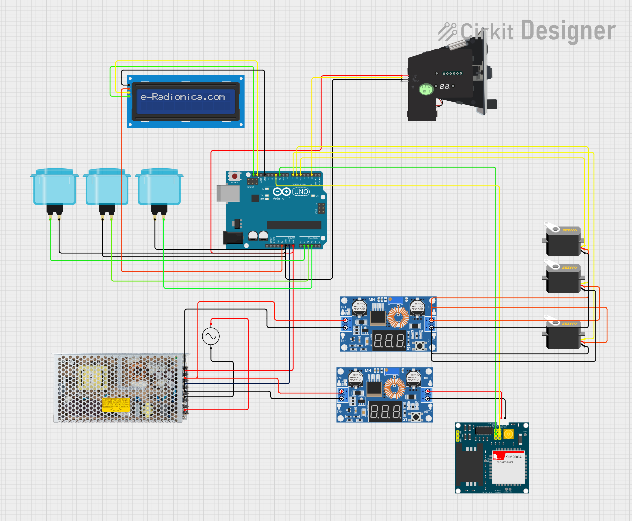 Open Project in Cirkit Designer
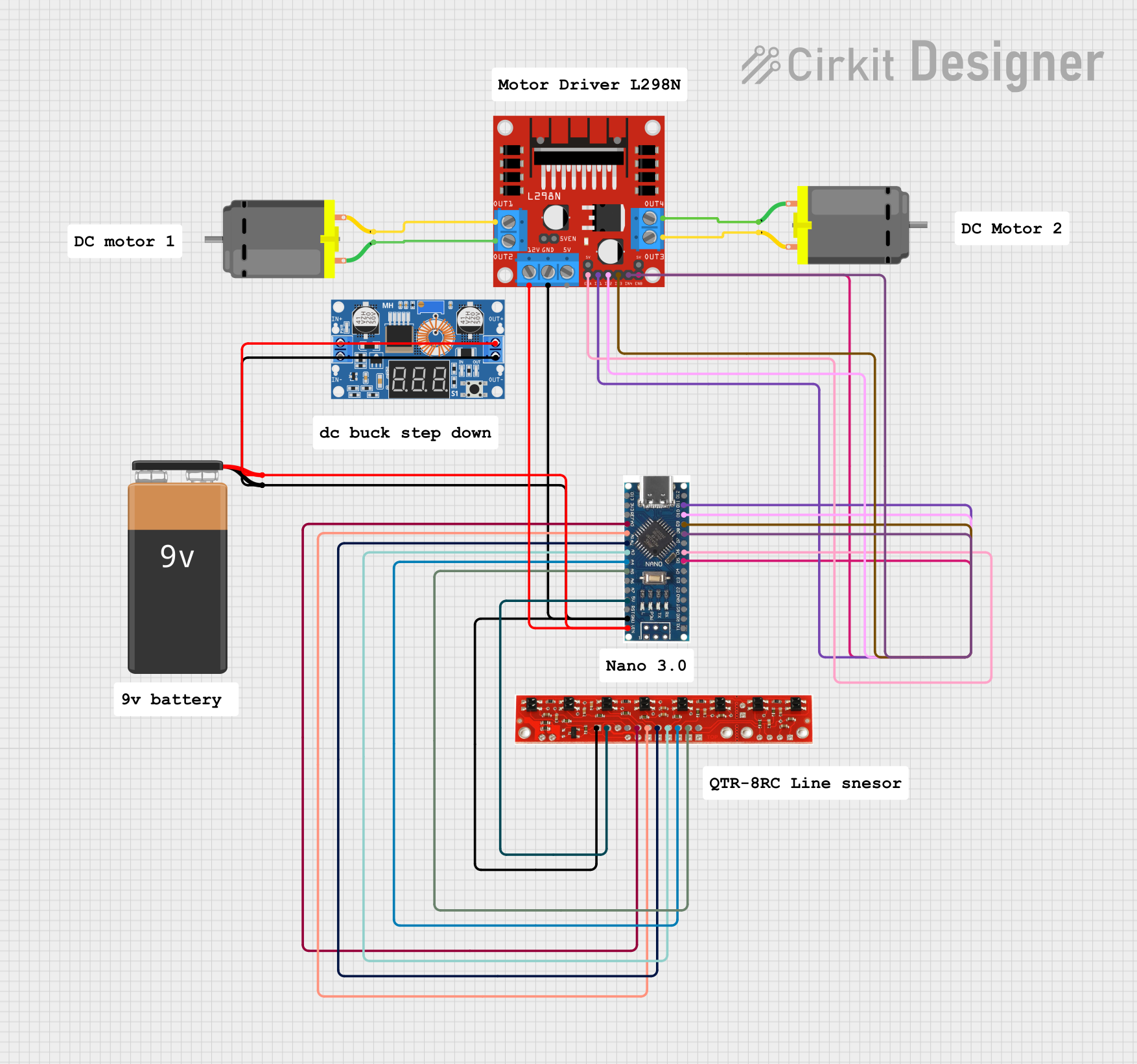 Open Project in Cirkit Designer
Explore Projects Built with PICAXE-40X2
Open Project in Cirkit DesignerOpen Project in Cirkit DesignerOpen Project in Cirkit DesignerOpen Project in Cirkit DesignerCommon Applications and Use Cases
- Robotics and automation projects
- Sensor data acquisition and processing
- Motor control systems
- LED displays and lighting control
- Educational tools for learning microcontroller programming
- Home automation systems
Technical Specifications
The following table outlines the key technical details of the PICAXE-40X2 microcontroller:
| Parameter | Specification |
|---|---|
| Manufacturer | Revolution Education Ltd |
| Part ID | PICAXE-40X2 |
| Operating Voltage | 3.0V to 5.5V |
| Clock Speed | Up to 64 MHz (internal resonator) |
| I/O Pins | 33 (Digital I/O) |
| ADC Channels | 12 (10-bit resolution) |
| PWM Outputs | 4 |
| Communication Interfaces | I2C, SPI, Serial (UART) |
| Program Memory | 4096 bytes |
| EEPROM | 256 bytes |
| Power Consumption | Low power (varies with clock speed) |
| Package Type | DIP-40 |
Pin Configuration and Descriptions
The PICAXE-40X2 features a 40-pin dual in-line package (DIP). Below is the pin configuration and description:
| Pin Number | Pin Name | Function |
|---|---|---|
| 1 | VSS | Ground |
| 11, 31 | VDD | Positive supply voltage |
| 2-9, 12-19 | Port B | Digital I/O, ADC (selectable) |
| 21-28 | Port C | Digital I/O, ADC (selectable) |
| 33-40 | Port D | Digital I/O |
| 10, 20, 30 | Reserved | Not connected (NC) |
| 22, 23 | PWM1, PWM2 | Pulse Width Modulation outputs |
| 24, 25 | I2C SDA, SCL | I2C communication lines |
| 26, 27 | Serial TX, RX | UART communication lines |
Usage Instructions
How to Use the PICAXE-40X2 in a Circuit
- Power Supply: Connect the VDD pin to a 3.0V-5.5V power source and the VSS pin to ground.
- Programming: Use the PICAXE Programming Editor software to write and upload code to the microcontroller via a USB-to-serial cable.
- I/O Connections: Connect sensors, actuators, or other devices to the I/O pins. Configure the pins as input or output in the code.
- Communication: Use the I2C, SPI, or UART interfaces for communication with other devices or microcontrollers.
Important Considerations and Best Practices
- Voltage Levels: Ensure that all connected devices operate within the PICAXE-40X2's voltage range (3.0V-5.5V).
- Pin Protection: Use resistors or other protective components to prevent damage to the I/O pins.
- Decoupling Capacitors: Place a 0.1 µF capacitor near the VDD and VSS pins to stabilize the power supply.
- Programming Cable: Use the official PICAXE USB programming cable for reliable code uploads.
Example Code for Arduino-like Functionality
Below is an example of a simple program to blink an LED connected to pin B.0:
' Blink an LED connected to pin B.0
' Ensure the LED has a current-limiting resistor (e.g., 330 ohms)

main:
    high B.0          ' Turn on the LED
    pause 1000        ' Wait for 1 second
    low B.0           ' Turn off the LED
    pause 1000        ' Wait for 1 second
    goto main         ' Repeat the loop
Troubleshooting and FAQs
Common Issues and Solutions
Microcontroller Not Responding
- Cause: Incorrect power supply or loose connections.
- Solution: Verify that the VDD and VSS pins are properly connected and the voltage is within the specified range.
Code Upload Fails
- Cause: Faulty programming cable or incorrect COM port selection.
- Solution: Check the USB-to-serial cable connection and ensure the correct COM port is selected in the programming software.
I/O Pins Not Working
- Cause: Pins not configured correctly in the code.
- Solution: Double-check the pin configuration in the program and ensure the pins are set as input or output as needed.
Communication Issues (I2C/SPI/UART)
- Cause: Incorrect wiring or mismatched baud rates.
- Solution: Verify the wiring and ensure the communication settings match between devices.
FAQs
Q: Can the PICAXE-40X2 be powered by batteries?
A: Yes, it can be powered by batteries as long as the voltage is within the 3.0V-5.5V range.
Q: What software is required to program the PICAXE-40X2?
A: The PICAXE Programming Editor or PICAXE Editor 6 software is used to write and upload code.
Q: Can I use the PICAXE-40X2 with an Arduino?
A: Yes, the PICAXE-40X2 can communicate with an Arduino via I2C, SPI, or UART interfaces.
Q: How many devices can be connected to the I2C bus?
A: The I2C bus supports multiple devices, but the total number depends on the addressable range and electrical limitations.
This concludes the documentation for the PICAXE-40X2 microcontroller.