Cirkit Designer
Your all-in-one circuit design IDE
Home /
Component Documentation
How to Use ftyrtyr: Examples, Pinouts, and Specs
Introduction
- The
ftyrtyris an electronic component manufactured by jfuf. Unfortunately, no official description or detailed information is available for this component, as it does not correspond to a widely recognized or standard circuit component. - Without specific details, this documentation will provide a general framework for understanding and working with unknown or custom components, which may be applicable to
ftyrtyr.
Explore Projects Built with ftyrtyr
Battery-Powered Line Following Robot with IR Sensors and Cytron URC10 Motor Controller

This circuit is a robotic control system that uses multiple IR sensors for line detection and obstacle avoidance, powered by a 3S LiPo battery. The Cytron URC10 motor driver, controlled by a microcontroller, drives two GM25 DC motors based on input from the sensors and a rocker switch, with a 7-segment panel voltmeter displaying the battery voltage.
Arduino-Controlled Motor System with Bluetooth Connectivity
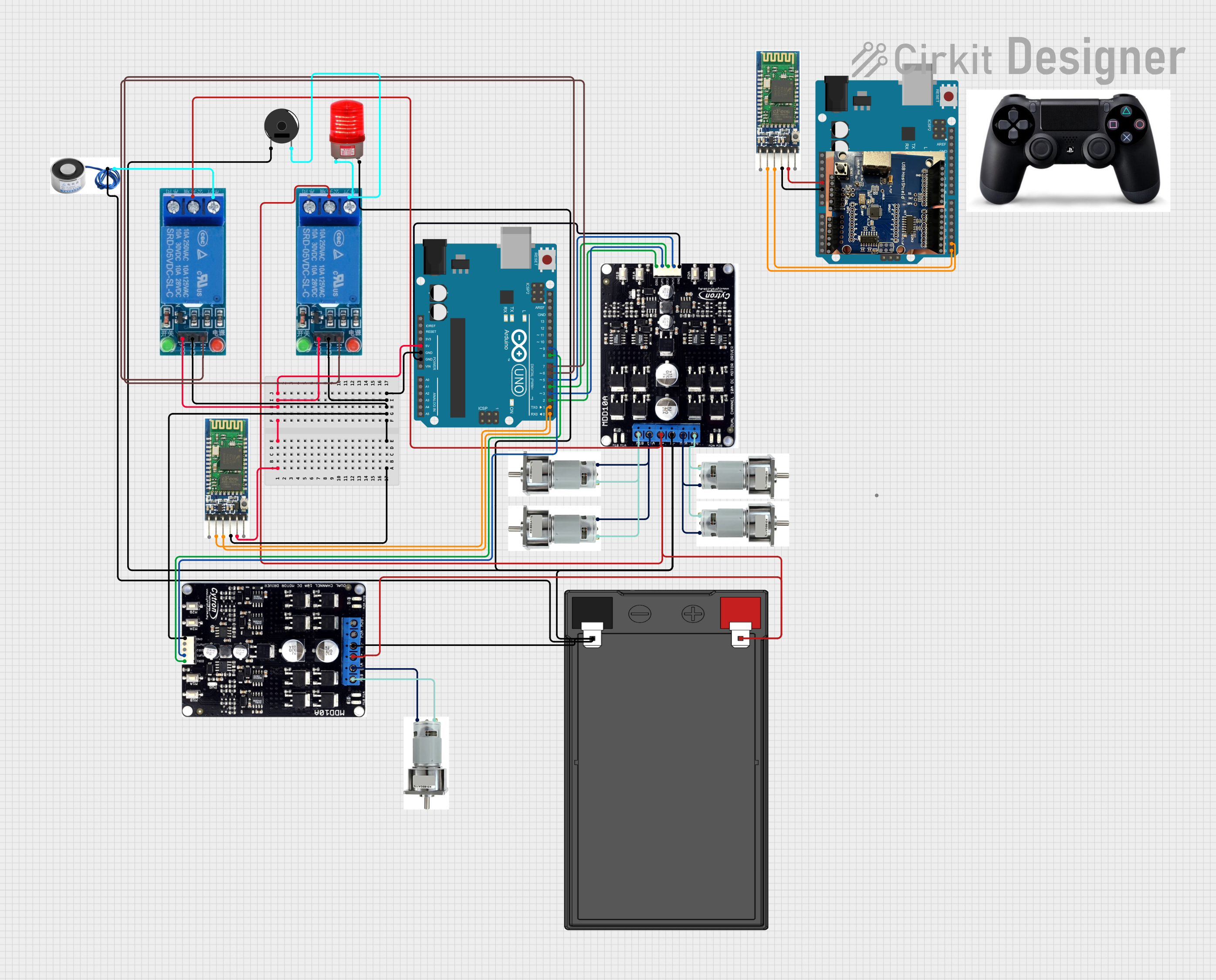
This is a motor control system with wireless communication capabilities, designed to operate multiple motors via Cytron motor drivers, controlled by Arduino UNOs. It includes relays for activating a light and buzzer, and uses Bluetooth for remote operation. The system's software is in the initial stages of development.
Arduino Mega 2560 Biometric Security System with Wi-Fi Connectivity
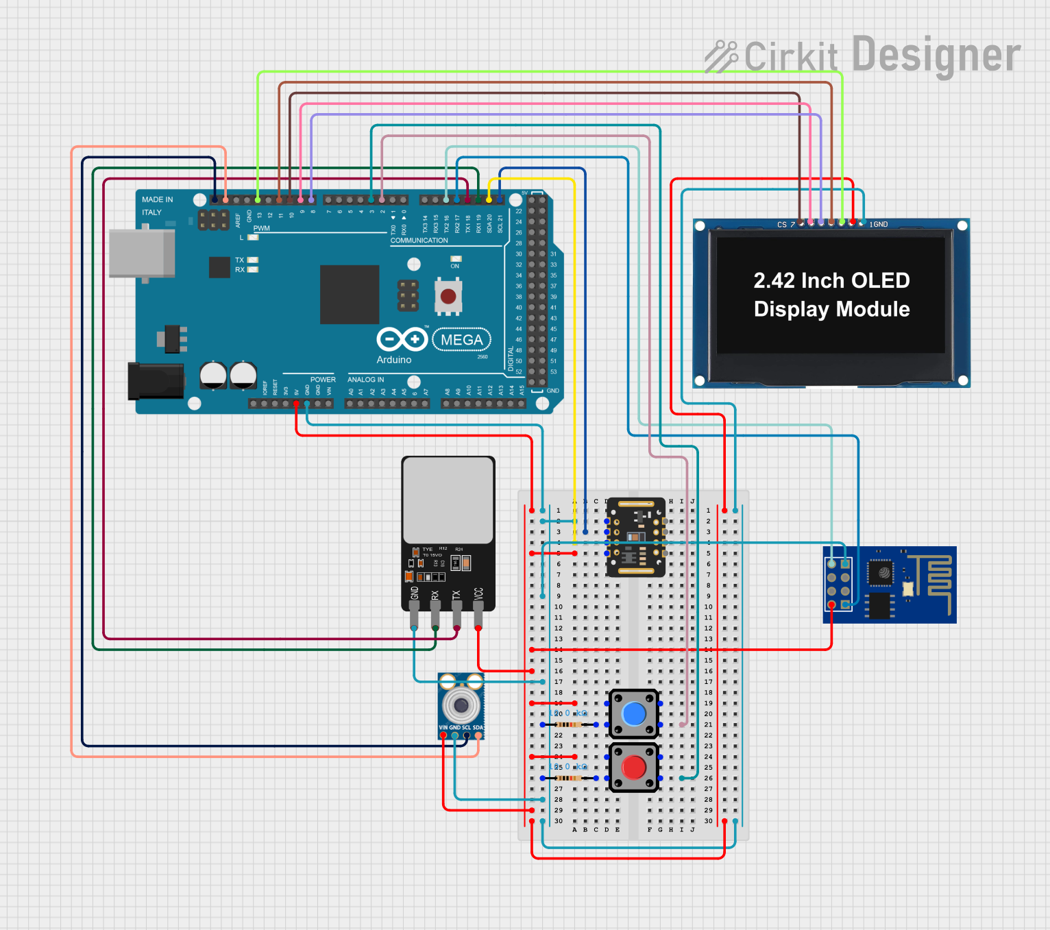
This is a multi-functional sensor system controlled by an Arduino Mega 2560, designed to read biometric data from a pulse oximeter and an infrared thermometer, authenticate using a fingerprint scanner, display information on an OLED screen, and transmit data wirelessly via an ESP8266 module. User inputs can be received through two pushbuttons, and the system's power distribution is managed through common ground and voltage supply nets.
Arduino Uno R3 Controlled Pan-Tilt Security Camera with Night Vision
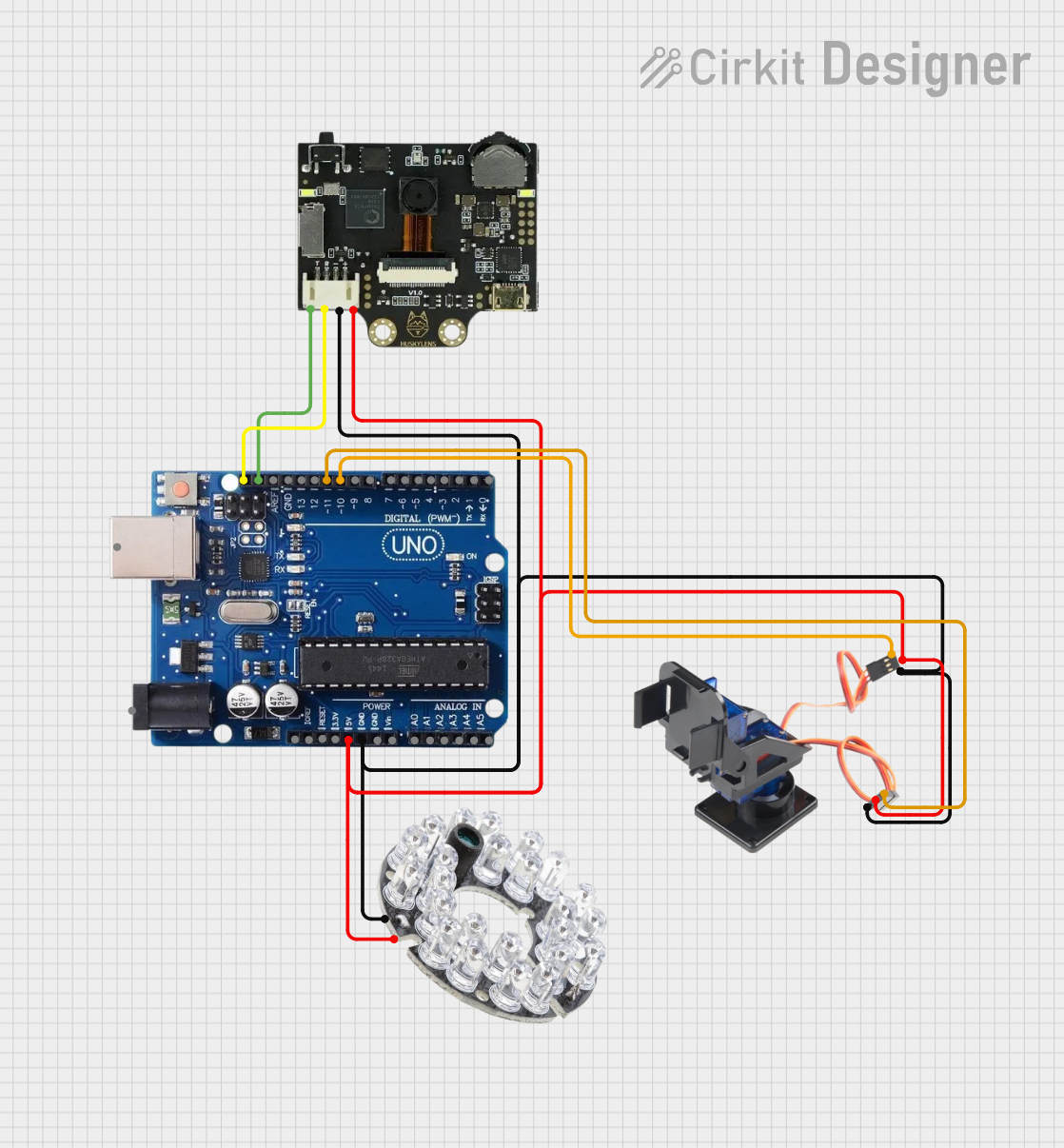
This circuit features an Arduino Uno R3 microcontroller connected to a Huskylens (an AI camera module), an IR LED Night Vision Ring, and a Tilt Pan module. The Huskylens is interfaced with the Arduino via I2C communication using the SDA and SCL lines, while the Tilt Pan module is controlled by the Arduino through digital pins 10 and 11 for signal and output control. The IR LED ring and Tilt Pan are powered directly from the Arduino's 5V output, and all components share a common ground.
Explore Projects Built with ftyrtyr
Battery-Powered Line Following Robot with IR Sensors and Cytron URC10 Motor Controller
This circuit is a robotic control system that uses multiple IR sensors for line detection and obstacle avoidance, powered by a 3S LiPo battery. The Cytron URC10 motor driver, controlled by a microcontroller, drives two GM25 DC motors based on input from the sensors and a rocker switch, with a 7-segment panel voltmeter displaying the battery voltage.
Arduino-Controlled Motor System with Bluetooth Connectivity
This is a motor control system with wireless communication capabilities, designed to operate multiple motors via Cytron motor drivers, controlled by Arduino UNOs. It includes relays for activating a light and buzzer, and uses Bluetooth for remote operation. The system's software is in the initial stages of development.
Arduino Mega 2560 Biometric Security System with Wi-Fi Connectivity
This is a multi-functional sensor system controlled by an Arduino Mega 2560, designed to read biometric data from a pulse oximeter and an infrared thermometer, authenticate using a fingerprint scanner, display information on an OLED screen, and transmit data wirelessly via an ESP8266 module. User inputs can be received through two pushbuttons, and the system's power distribution is managed through common ground and voltage supply nets.
Arduino Uno R3 Controlled Pan-Tilt Security Camera with Night Vision
This circuit features an Arduino Uno R3 microcontroller connected to a Huskylens (an AI camera module), an IR LED Night Vision Ring, and a Tilt Pan module. The Huskylens is interfaced with the Arduino via I2C communication using the SDA and SCL lines, while the Tilt Pan module is controlled by the Arduino through digital pins 10 and 11 for signal and output control. The IR LED ring and Tilt Pan are powered directly from the Arduino's 5V output, and all components share a common ground.
Technical Specifications
- Since no official specifications are available for
ftyrtyr, users are encouraged to test the component using appropriate tools (e.g., multimeter, oscilloscope) to determine its electrical characteristics. - Below is a placeholder table for pin configuration, which can be updated based on user testing or manufacturer-provided details.
| Pin Number | Pin Name | Description |
|---|---|---|
| 1 | TBD | To be determined by testing |
| 2 | TBD | To be determined by testing |
| 3 | TBD | To be determined by testing |
Note: Always consult the manufacturer (jfuf) for any available datasheets or technical support.
Usage Instructions
Step 1: Identify the Component's Functionality
- Use a multimeter to measure resistance, continuity, or voltage drop across pins.
- If the component is active (e.g., IC, transistor), power it with a low voltage and observe its behavior.
Step 2: Test in a Circuit
- Begin with a simple test circuit to determine the component's role (e.g., resistor, capacitor, diode, etc.).
- Use a breadboard for easy adjustments and testing.
Step 3: Observe Polarity (if applicable)
- If the component has polarity (e.g., diodes, electrolytic capacitors), ensure correct orientation to avoid damage.
Step 4: Connect to Arduino (if applicable)
- If the component is compatible with microcontrollers, connect it to an Arduino UNO for further testing.
- Below is a generic Arduino code snippet for reading an unknown component's behavior (e.g., voltage or resistance):
// Generic Arduino code to read voltage across a component
// Connect one terminal of the component to A0 and the other to GND

const int sensorPin = A0; // Analog pin connected to the component
int sensorValue = 0;      // Variable to store the analog reading

void setup() {
  Serial.begin(9600); // Initialize serial communication
}

void loop() {
  sensorValue = analogRead(sensorPin); // Read the analog value
  float voltage = sensorValue * (5.0 / 1023.0); // Convert to voltage
  Serial.print("Voltage across component: ");
  Serial.print(voltage);
  Serial.println(" V");
  delay(1000); // Wait for 1 second before the next reading
}
Important Considerations:
- Always start with low voltage and current to avoid damaging the component.
- Use appropriate safety precautions when working with unknown components.
Troubleshooting and FAQs
Issue: The component does not function as expected.
- Solution: Verify the pin configuration and ensure proper connections. Test the component with a multimeter to confirm its functionality.
Issue: The component overheats during operation.
- Solution: Reduce the input voltage or current. Check for incorrect polarity or short circuits.
Issue: No response or output from the component.
- Solution: Double-check the circuit design and ensure the component is not damaged. Consult the manufacturer for additional support.
FAQ: How can I determine the exact specifications of
ftyrtyr?- Answer: Contact the manufacturer (jfuf) for datasheets or technical documentation. Alternatively, use testing equipment to measure its characteristics.
FAQ: Can I use
ftyrtyrwith an Arduino?- Answer: If the component's functionality is determined to be compatible with Arduino, it can be integrated into projects. Use caution and test thoroughly before deployment.
Tip: Document your findings and share them with the community to help others working with
ftyrtyr.