How to Use linksys ethernet switches: Examples, Pinouts, and Specs
Introduction
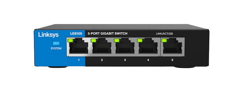
Linksys Ethernet switches are networking devices designed to connect multiple devices within a local area network (LAN). These switches enable seamless communication between connected devices, such as computers, printers, and servers, by providing multiple Ethernet ports for wired connections. Known for their reliability, ease of use, and robust performance, Linksys Ethernet switches are widely used in both home and office environments.
Explore Projects Built with linksys ethernet switches


Explore Projects Built with linksys ethernet switches
Common Applications and Use Cases
- Expanding the number of Ethernet ports in a network.
- Connecting multiple devices in a home or office LAN.
- Enhancing network performance by reducing congestion.
- Supporting high-speed data transfer for gaming, streaming, and file sharing.
- Integrating wired devices into a wireless network via a router.
Technical Specifications
Below are the general technical specifications for Linksys Ethernet switches. Specific models may vary slightly, so always refer to the product manual for exact details.
Key Technical Details
- Port Count: 5, 8, 16, or 24 Ethernet ports (depending on the model).
- Port Type: RJ-45, supporting 10/100/1000 Mbps (Gigabit Ethernet).
- Switching Capacity: Up to 48 Gbps (varies by model).
- Power Supply: External power adapter (typically 12V DC, 1A or 2A).
- Standards Supported: IEEE 802.3, 802.3u, 802.3ab, 802.3x.
- Auto-MDI/MDIX: Supported on all ports (eliminates the need for crossover cables).
- QoS (Quality of Service): Prioritizes traffic for smoother performance.
- Operating Temperature: 0°C to 40°C (32°F to 104°F).
- Dimensions: Varies by model (e.g., 5-port models are compact, while 24-port models are rack-mountable).
Pin Configuration and Descriptions
Linksys Ethernet switches use standard RJ-45 Ethernet ports. Below is the pinout for these ports:
| Pin Number | Signal Name | Description |
|---|---|---|
| 1 | TX+ | Transmit Data Positive |
| 2 | TX- | Transmit Data Negative |
| 3 | RX+ | Receive Data Positive |
| 4 | BI_D3+ | Bidirectional Data Line 3 Positive |
| 5 | BI_D3- | Bidirectional Data Line 3 Negative |
| 6 | RX- | Receive Data Negative |
| 7 | BI_D4+ | Bidirectional Data Line 4 Positive |
| 8 | BI_D4- | Bidirectional Data Line 4 Negative |
Usage Instructions
How to Use the Component in a Network
- Unbox and Inspect: Ensure the switch and its power adapter are undamaged.
- Placement: Place the switch in a well-ventilated area to prevent overheating.
- Power Connection: Connect the power adapter to the switch and plug it into a power outlet.
- Device Connections:
- Use Ethernet cables to connect devices (e.g., computers, printers) to the switch's ports.
- If connecting to a router, use one port to link the switch to the router for internet access.
- Power On: Turn on the switch (if it has a power button) and verify that the power LED is lit.
- Check Connectivity: Ensure the port LEDs light up when devices are connected, indicating active links.
Important Considerations and Best Practices
- Cable Quality: Use high-quality Cat5e or Cat6 Ethernet cables for optimal performance.
- Avoid Overloading: Do not exceed the switch's maximum port capacity.
- Ventilation: Ensure proper airflow around the switch to prevent overheating.
- Firmware Updates: Check for firmware updates on the Linksys website to ensure the switch operates with the latest features and security patches.
- QoS Configuration: If supported, configure QoS settings to prioritize critical traffic, such as VoIP or video streaming.
Example: Connecting to an Arduino UNO
While Linksys Ethernet switches are not directly programmable, they can be used to connect an Arduino UNO with an Ethernet shield to a network. Below is an example Arduino sketch for sending data over a network:
#include <SPI.h>
#include <Ethernet.h>

// MAC address and IP address for the Ethernet shield
byte mac[] = { 0xDE, 0xAD, 0xBE, 0xEF, 0xFE, 0xED };
IPAddress ip(192, 168, 1, 177);

// Initialize the Ethernet server on port 80
EthernetServer server(80);

void setup() {
  // Start the Ethernet connection
  Ethernet.begin(mac, ip);
  // Start the server
  server.begin();
  Serial.begin(9600);
  Serial.println("Server is ready at 192.168.1.177");
}

void loop() {
  // Listen for incoming clients
  EthernetClient client = server.available();
  if (client) {
    Serial.println("New client connected");
    // Send a response to the client
    client.println("Hello from Arduino!");
    delay(100);
    client.stop(); // Close the connection
  }
}
Note: Connect the Ethernet shield to the Linksys switch using an Ethernet cable. Ensure the switch is connected to a router for network access.
Troubleshooting and FAQs
Common Issues and Solutions
No Power LED:
- Ensure the power adapter is securely connected to the switch and the outlet.
- Verify that the outlet is functional by testing with another device.
No Port LED When Device is Connected:
- Check the Ethernet cable for damage or improper connection.
- Ensure the connected device is powered on and its network adapter is enabled.
- Try a different port on the switch.
Slow Network Speeds:
- Use Cat6 cables for Gigabit speeds.
- Check for network congestion or excessive traffic.
- Ensure the connected devices support the desired speed (e.g., 1000 Mbps).
Overheating:
- Place the switch in a well-ventilated area.
- Avoid stacking other devices on top of the switch.
FAQs
Q: Can I use a Linksys Ethernet switch without a router?
A: Yes, the switch can connect devices within a LAN without a router. However, a router is required for internet access.
Q: Does the switch support PoE (Power over Ethernet)?
A: Some Linksys models support PoE. Check the product specifications for PoE compatibility.
Q: How do I reset the switch?
A: Most Linksys switches do not have a reset button. Simply power cycle the device by unplugging and reconnecting the power adapter.
Q: Can I mount the switch on a wall?
A: Many Linksys switches include mounting holes for wall installation. Refer to the user manual for mounting instructions.