How to Use Hailege 12 Volt SPST Relay: Examples, Pinouts, and Specs
Introduction
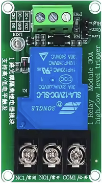
The Hailege 12 Volt SPST Relay (Manufacturer Part ID: 1) is a single pole, single throw relay designed to control electrical circuits by opening or closing them in response to a 12V DC signal. This relay acts as an electrically operated switch, allowing low-power control signals to manage higher-power circuits safely and efficiently.
Explore Projects Built with Hailege 12 Volt SPST Relay
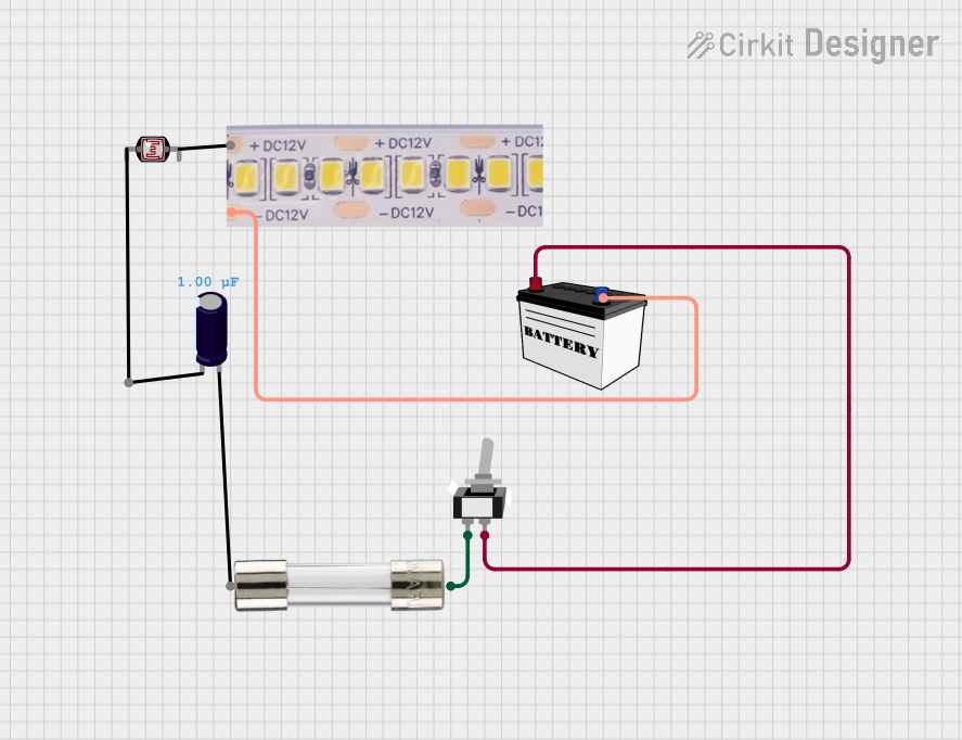
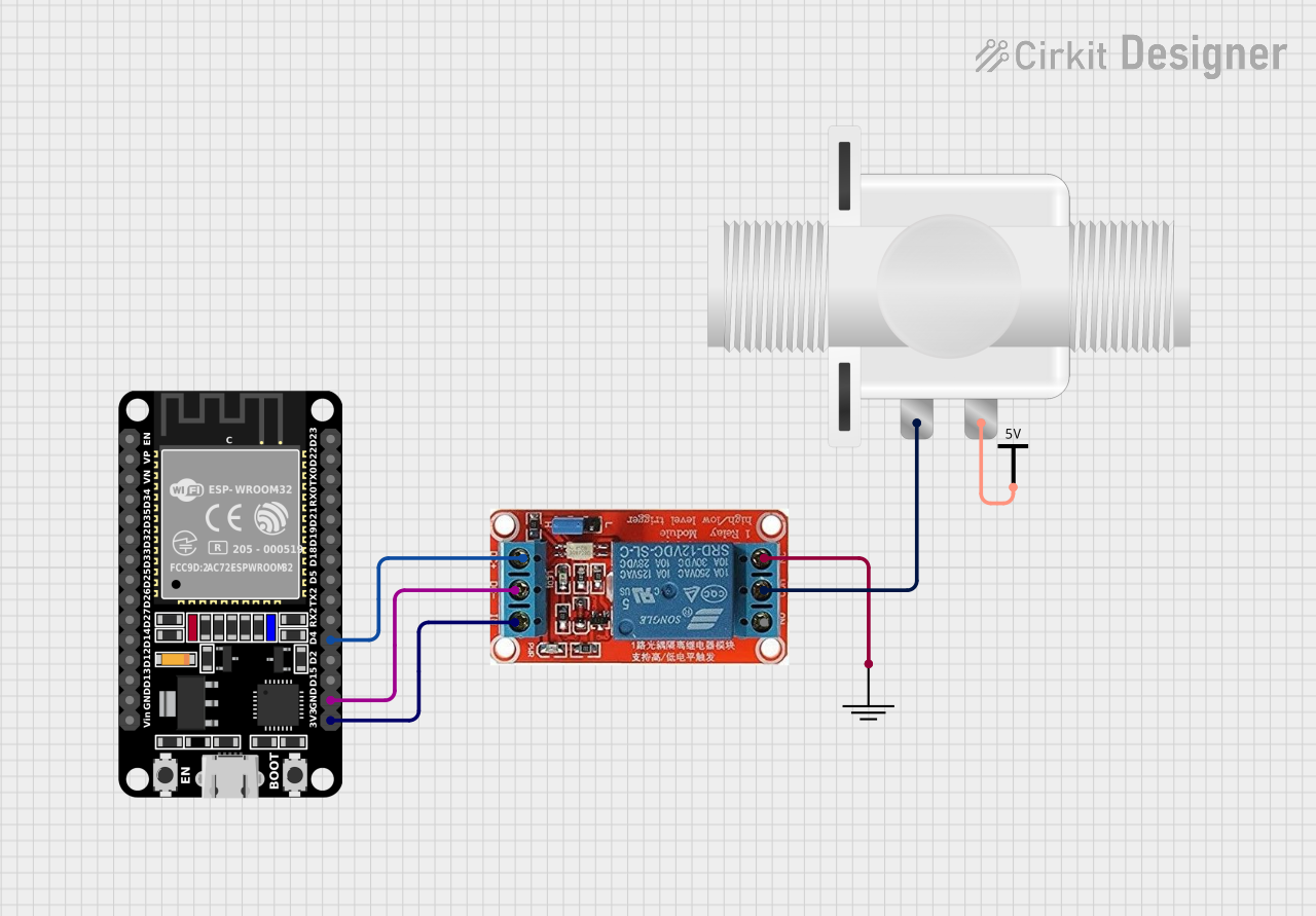


Explore Projects Built with Hailege 12 Volt SPST Relay
Common Applications and Use Cases
- Automotive Systems: Controlling lights, horns, or other 12V devices.
- Home Automation: Switching appliances or lights remotely.
- Industrial Control: Managing motors, solenoids, or other high-power devices.
- Microcontroller Projects: Interfacing with Arduino, Raspberry Pi, or other development boards to control external devices.
Technical Specifications
Key Technical Details
- Operating Voltage: 12V DC
- Coil Resistance: ~400 Ohms
- Contact Type: Single Pole Single Throw (SPST)
- Contact Rating: 10A at 250V AC or 10A at 30V DC
- Switching Voltage (Max): 250V AC / 30V DC
- Switching Current (Max): 10A
- Relay Type: Electromechanical
- Dimensions: 28mm x 12mm x 15mm (L x W x H)
- Weight: ~15g
- Insulation Resistance: ≥100MΩ at 500V DC
- Dielectric Strength: 500V AC (coil to contact)
Pin Configuration and Descriptions
The Hailege 12 Volt SPST Relay has 5 pins, as described in the table below:
| Pin Number | Name | Description |
|---|---|---|
| 1 | Coil (+) | Positive terminal of the relay coil. Connect to 12V DC to energize the relay. |
| 2 | Coil (-) | Negative terminal of the relay coil. Connect to ground. |
| 3 | Common (COM) | Common terminal for the relay switch. |
| 4 | Normally Open (NO) | The terminal that connects to COM when the relay is energized. |
| 5 | Not Used | This pin is not connected internally and can be ignored. |
Usage Instructions
How to Use the Component in a Circuit
- Power the Relay: Connect the coil pins (1 and 2) to a 12V DC power source. Pin 1 should be connected to the positive terminal, and Pin 2 to ground.
- Control the Circuit: Connect the device or load to the Common (COM) and Normally Open (NO) pins. When the relay is energized, the circuit between COM and NO will close, allowing current to flow.
- Driving the Relay: Use a transistor or relay driver IC to control the relay from a microcontroller or low-power circuit. A flyback diode should be placed across the coil terminals to protect the driving circuit from voltage spikes.
Important Considerations and Best Practices
- Flyback Diode: Always use a flyback diode (e.g., 1N4007) across the coil terminals to prevent damage to the driving circuit from back EMF when the relay is de-energized.
- Current Rating: Ensure the connected load does not exceed the relay's maximum current rating of 10A.
- Isolation: Maintain proper electrical isolation between the control circuit and the high-power circuit to avoid damage or hazards.
- Mounting: Secure the relay in place to prevent vibration or movement in automotive or industrial applications.
Example: Connecting to an Arduino UNO
Below is an example of how to control the Hailege 12 Volt SPST Relay using an Arduino UNO:
// Example: Controlling a 12V SPST Relay with Arduino UNO
// Pin 7 is used to control the relay via a transistor driver circuit.

const int relayPin = 7; // Define the pin connected to the relay driver circuit

void setup() {
  pinMode(relayPin, OUTPUT); // Set the relay pin as an output
  digitalWrite(relayPin, LOW); // Ensure the relay is off initially
}

void loop() {
  digitalWrite(relayPin, HIGH); // Turn the relay on
  delay(5000); // Keep the relay on for 5 seconds
  digitalWrite(relayPin, LOW); // Turn the relay off
  delay(5000); // Keep the relay off for 5 seconds
}
Note: Use a transistor (e.g., 2N2222) and a base resistor (e.g., 1kΩ) to drive the relay from the Arduino, as the Arduino's GPIO pins cannot supply enough current to energize the relay directly.
Troubleshooting and FAQs
Common Issues and Solutions
Relay Not Switching:
- Cause: Insufficient voltage or current to the coil.
- Solution: Verify that the coil is receiving 12V DC and check the power supply's current capacity.
Relay Stuck in ON or OFF Position:
- Cause: Damaged or worn-out relay contacts.
- Solution: Replace the relay if the contacts are damaged or worn.
Microcontroller Resetting When Relay Activates:
- Cause: Voltage spikes from the relay coil.
- Solution: Ensure a flyback diode is installed across the coil terminals.
Load Not Turning On/Off:
- Cause: Incorrect wiring of the load to the relay.
- Solution: Double-check the connections to the COM and NO pins.
FAQs
Q: Can this relay handle AC loads?
- A: Yes, the relay can handle AC loads up to 250V at 10A.
Q: Can I use this relay with a 5V microcontroller?
- A: Yes, but you will need a transistor or relay driver circuit to step up the control signal to 12V.
Q: Is the relay suitable for continuous operation?
- A: Yes, but ensure proper ventilation and avoid exceeding the rated current to prevent overheating.
Q: Can I use this relay for switching high-frequency signals?
- A: No, this relay is not designed for high-frequency switching and is better suited for low-frequency or static applications.