How to Use Z80 ACPU: Examples, Pinouts, and Specs
Introduction
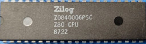
The Z80 ACPU, manufactured by Zilog (Part ID: Z80C8400A6B), is a highly versatile 8-bit microprocessor that played a pivotal role in the evolution of computing during the late 1970s and 1980s. It features a 16-bit address bus, enabling access to 64KB of memory, and supports a robust instruction set for efficient and flexible programming. Its design makes it suitable for a wide range of applications, from home computers to embedded systems.
Explore Projects Built with Z80 ACPU
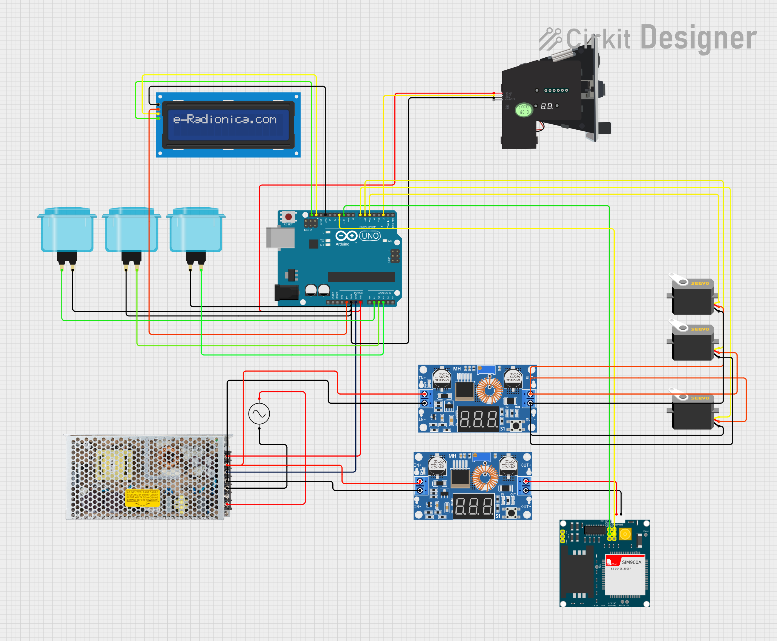
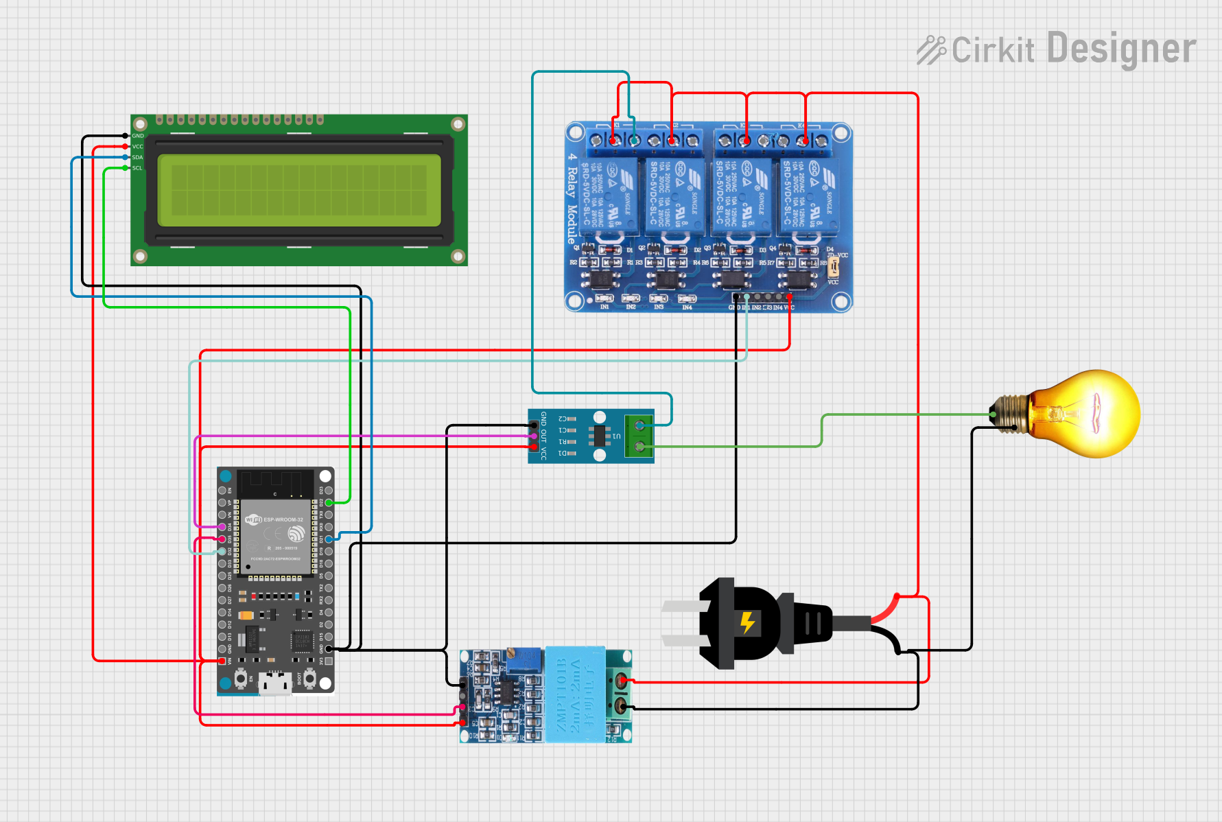


Explore Projects Built with Z80 ACPU
Common Applications and Use Cases
- Home Computers: Widely used in early personal computers such as the Sinclair ZX Spectrum and TRS-80.
- Embedded Systems: Ideal for control systems, industrial automation, and consumer electronics.
- Educational Tools: Frequently used in teaching microprocessor architecture and assembly programming.
- Retrocomputing Projects: Popular among hobbyists for recreating vintage computing systems.
Technical Specifications
Key Technical Details
| Parameter | Value |
|---|---|
| Manufacturer | Zilog |
| Part ID | Z80C8400A6B |
| Architecture | 8-bit |
| Address Bus Width | 16-bit (64KB addressable memory) |
| Data Bus Width | 8-bit |
| Clock Speed | Up to 8 MHz |
| Instruction Set | Rich CISC (Complex Instruction Set Computing) |
| Power Supply Voltage | 5V ± 10% |
| Power Consumption | ~100 mW (at 4 MHz) |
| Operating Temperature | 0°C to 70°C |
| Package Type | 40-pin DIP (Dual Inline Package) |
Pin Configuration and Descriptions
The Z80 ACPU has 40 pins, each serving a specific function. Below is a summary of the pin configuration:
| Pin Number | Pin Name | Description |
|---|---|---|
| 1 | A15 | Address line 15 (MSB of the address bus) |
| 2-15 | A14-A0 | Address lines 14 to 0 (used to address memory and I/O devices) |
| 16 | GND | Ground (0V reference) |
| 17 | D0 | Data line 0 (LSB of the data bus) |
| 18-25 | D1-D7 | Data lines 1 to 7 (used for data transfer) |
| 26 | /MREQ | Memory Request (active low, indicates memory access) |
| 27 | /IORQ | I/O Request (active low, indicates I/O access) |
| 28 | /RD | Read (active low, indicates data is being read from memory or I/O) |
| 29 | /WR | Write (active low, indicates data is being written to memory or I/O) |
| 30 | /HALT | Halt (active low, indicates the processor is in a halt state) |
| 31 | /WAIT | Wait (active low, used to synchronize slower peripherals) |
| 32 | /INT | Interrupt Request (active low, used to signal an interrupt) |
| 33 | /NMI | Non-Maskable Interrupt (active low, high-priority interrupt) |
| 34 | /RESET | Reset (active low, initializes the processor) |
| 35 | CLK | Clock Input (provides the timing signal for the processor) |
| 36 | /BUSREQ | Bus Request (active low, used to request control of the address and data buses) |
| 37 | /BUSACK | Bus Acknowledge (active low, indicates the processor has relinquished the bus) |
| 38 | /M1 | Machine Cycle 1 (active low, indicates the first cycle of an instruction fetch) |
| 39 | /RFSH | Refresh (active low, used for dynamic RAM refresh) |
| 40 | VCC | Power Supply (+5V) |
Usage Instructions
How to Use the Z80 ACPU in a Circuit
- Power Supply: Connect the VCC pin (Pin 40) to a regulated +5V power supply and the GND pin (Pin 16) to ground.
- Clock Signal: Provide a stable clock signal to the CLK pin (Pin 35). The clock frequency should not exceed the rated maximum (e.g., 8 MHz).
- Memory and I/O: Connect the address lines (A0-A15) to memory or I/O devices. Use the /MREQ and /IORQ pins to differentiate between memory and I/O operations.
- Data Bus: Connect the data lines (D0-D7) to the data bus of the system. Ensure proper pull-up or pull-down resistors if required.
- Control Signals: Use the /RD and /WR pins to manage read and write operations. The /RESET pin should be connected to a reset circuit for initialization.
- Interrupts: Connect the /INT and /NMI pins to external interrupt sources if needed. Ensure proper handling of interrupt priorities in your software.
Important Considerations and Best Practices
- Decoupling Capacitors: Place decoupling capacitors (e.g., 0.1 µF) near the VCC and GND pins to reduce noise and stabilize the power supply.
- Clock Stability: Use a crystal oscillator or a stable clock generator to ensure reliable operation.
- Bus Arbitration: If multiple devices share the address and data buses, implement proper bus arbitration using the /BUSREQ and /BUSACK pins.
- Dynamic RAM: If using dynamic RAM, connect the /RFSH pin to the memory refresh circuitry.
Example Code for Arduino UNO
Although the Z80 ACPU is not directly compatible with Arduino, you can use an Arduino UNO to simulate control signals for basic operations. Below is an example of generating a clock signal:
// Arduino UNO code to generate a clock signal for the Z80 ACPU
const int clockPin = 9; // Pin 9 connected to the CLK pin of the Z80

void setup() {
  pinMode(clockPin, OUTPUT); // Set clockPin as an output
}

void loop() {
  digitalWrite(clockPin, HIGH); // Set clock signal HIGH
  delayMicroseconds(1);        // 1 µs delay for half clock period (500 kHz clock)
  digitalWrite(clockPin, LOW); // Set clock signal LOW
  delayMicroseconds(1);        // 1 µs delay for half clock period
}
Troubleshooting and FAQs
Common Issues and Solutions
Processor Not Starting:
- Cause: Improper reset signal.
- Solution: Ensure the /RESET pin is held low for at least 10 clock cycles during power-up.
Unstable Operation:
- Cause: Noisy power supply or clock signal.
- Solution: Add decoupling capacitors and use a stable clock source.
Memory Access Errors:
- Cause: Incorrect address or control signal connections.
- Solution: Verify the connections of address lines (A0-A15) and control signals (/MREQ, /RD, /WR).
Interrupts Not Working:
- Cause: Improper interrupt handling in software.
- Solution: Check the interrupt vector table and ensure proper acknowledgment of interrupts.
FAQs
Q: Can the Z80 ACPU address more than 64KB of memory?
- A: Not directly. However, bank switching techniques can be used to extend the addressable memory.
Q: What is the maximum clock speed of the Z80 ACPU?
- A: The Z80C8400A6B variant supports a maximum clock speed of 8 MHz.
Q: Is the Z80 ACPU still in production?
- A: Yes, Zilog continues to manufacture the Z80 series for use in legacy systems and new designs.
Q: Can the Z80 ACPU be used with modern peripherals?
- A: Yes, with proper interfacing circuits, the Z80 can communicate with modern peripherals.