How to Use TPS61088: Examples, Pinouts, and Specs
Introduction
The TPS61088 is a high-efficiency boost converter designed to step up low input voltages to higher output voltages. It features a wide input voltage range, adjustable output voltage, and a compact package, making it ideal for battery-powered applications and portable devices. With its high efficiency and robust design, the TPS61088 is commonly used in applications such as power banks, portable medical devices, and industrial equipment requiring stable voltage regulation.
Explore Projects Built with TPS61088


Explore Projects Built with TPS61088
Common Applications:
- Power banks and portable chargers
- Battery-powered medical devices
- Industrial and IoT devices
- LED backlighting
- Wireless communication modules
Technical Specifications
Key Technical Details:
- Input Voltage Range: 2.7 V to 12 V
- Output Voltage Range: Up to 12.6 V (adjustable)
- Switching Frequency: 200 kHz to 2.2 MHz
- Maximum Output Current: Up to 10 A (depending on input/output conditions)
- Efficiency: Up to 96%
- Quiescent Current: 0.9 mA (typical)
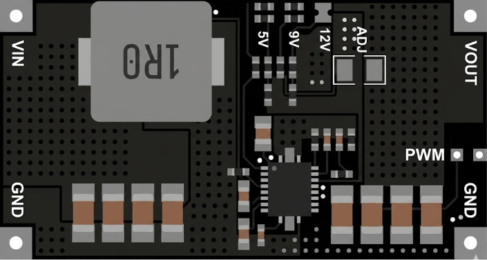
- Package: 3 mm × 3 mm VQFN-16
Pin Configuration and Descriptions:
The TPS61088 is available in a 16-pin VQFN package. Below is the pin configuration:
| Pin Number | Pin Name | Description |
|---|---|---|
| 1 | SW | Switching node. Connect to the inductor and Schottky diode. |
| 2 | VIN | Input voltage supply. Connect to the input power source. |
| 3 | EN | Enable pin. Drive high to enable the device, low to disable. |
| 4 | FB | Feedback pin. Connect to a resistor divider to set the output voltage. |
| 5 | COMP | Compensation pin. Connect a capacitor and resistor for loop stability. |
| 6 | SS | Soft-start pin. Connect a capacitor to control the startup time. |
| 7 | GND | Ground. Connect to the system ground plane. |
| 8 | PG | Power good indicator. Open-drain output; high when output voltage is stable. |
| 9-12 | NC | No connection. Leave these pins floating or connect to ground. |
| 13 | VOUT | Output voltage. Connect to the load and output capacitor. |
| 14 | MODE | Mode selection pin. High for forced PWM mode, low for PFM mode. |
| 15 | ILIM | Current limit pin. Connect a resistor to set the peak current limit. |
| 16 | AGND | Analog ground. Connect to the system ground plane. |
Usage Instructions
How to Use the TPS61088 in a Circuit:
Input and Output Capacitors:
- Use low-ESR ceramic capacitors for both input and output to ensure stable operation.
- Recommended values: 10 µF to 22 µF for input and 22 µF to 100 µF for output.
Inductor Selection:
- Choose an inductor with a saturation current higher than the peak current limit.
- Typical inductance range: 1 µH to 2.2 µH.
Feedback Resistor Divider:
- Use two resistors to set the output voltage. The formula is: [ V_{OUT} = V_{FB} \times \left(1 + \frac{R1}{R2}\right) ] where ( V_{FB} ) is 1.2 V (reference voltage).
Enable Pin:
- Drive the EN pin high (logic level > 1.2 V) to enable the device.
- Pull it low (< 0.4 V) to disable the device.
Soft-Start:
- Connect a capacitor to the SS pin to control the startup time. A larger capacitor results in a slower startup.
Mode Selection:
- Connect the MODE pin high for forced PWM mode (better noise performance).
- Connect it low for PFM mode (higher efficiency at light loads).
Example Circuit:
Below is a basic circuit diagram for the TPS61088:
VIN ----[10 µF]----+----[Inductor]----+---- VOUT
                   |                  |
                  GND                FB (via resistor divider)
Arduino UNO Example Code:
If the TPS61088 is used to power an Arduino UNO, ensure the output voltage is set to 5 V. Below is an example code to monitor the power good (PG) pin:
// Define the pin connected to the PG (Power Good) pin of TPS61088
const int pgPin = 2; // Connect PG pin to Arduino digital pin 2

void setup() {
  pinMode(pgPin, INPUT); // Set PG pin as input
  Serial.begin(9600);    // Initialize serial communication
}

void loop() {
  int pgStatus = digitalRead(pgPin); // Read the PG pin status

  if (pgStatus == HIGH) {
    // PG pin is high, output voltage is stable
    Serial.println("TPS61088 Output Voltage is Stable.");
  } else {
    // PG pin is low, output voltage is not stable
    Serial.println("TPS61088 Output Voltage is NOT Stable.");
  }

  delay(1000); // Wait for 1 second before checking again
}
Important Considerations:
- Ensure the input voltage is within the specified range (2.7 V to 12 V).
- Use proper PCB layout techniques to minimize noise and ensure stable operation.
- Place input and output capacitors as close as possible to the device pins.
- Avoid exceeding the maximum output current to prevent damage.
Troubleshooting and FAQs
Common Issues and Solutions:
Output Voltage is Unstable:
- Check the feedback resistor divider for correct values.
- Ensure input and output capacitors are of the recommended type and value.
- Verify proper grounding and PCB layout.
Device Overheating:
- Ensure the inductor and capacitors are rated for the required current.
- Check for excessive input voltage or output current.
No Output Voltage:
- Verify the EN pin is driven high.
- Check for proper connections to the input power source and load.
Low Efficiency:
- Use low-ESR capacitors and an inductor with low DC resistance.
- Ensure the MODE pin is configured correctly for the desired operating mode.
FAQs:
Q1: Can the TPS61088 be used to power a 12 V LED strip?
A1: Yes, as long as the input voltage and current requirements are within the device's specifications.
Q2: What happens if the input voltage drops below 2.7 V?
A2: The device may stop operating or enter undervoltage lockout (UVLO) mode to protect itself.
Q3: How do I calculate the soft-start time?
A3: The soft-start time can be approximated using the formula:
[
t_{SS} = \frac{C_{SS} \times V_{REF}}{I_{SS}}
]
where ( C_{SS} ) is the soft-start capacitor, ( V_{REF} ) is 1.2 V, and ( I_{SS} ) is the soft-start charging current (typically 5 µA).
By following this documentation, users can effectively integrate the TPS61088 into their designs and troubleshoot common issues.