Cirkit Designer Logo
Cirkit Designer
Your all-in-one circuit design IDE
Home / 
Component Documentation

How to Use opa348 sot: Examples, Pinouts, and Specs

Image of opa348 sot
Cirkit Designer LogoDesign with opa348 sot in Cirkit Designer

Introduction

The OPA348 is a single-supply, low-power operational amplifier (op-amp) designed for precision applications. It features rail-to-rail input and output capabilities, making it ideal for low-voltage systems. The OPA348 is housed in a compact SOT-23 package, which is suitable for space-constrained designs. Its low quiescent current and high input impedance make it a versatile choice for battery-powered devices, signal conditioning, and sensor interfacing.

Explore Projects Built with opa348 sot

Use Cirkit Designer to design, explore, and prototype these projects online. Some projects support real-time simulation. Click "Open Project" to start designing instantly!
ESP32-S3 GPS and Wind Speed Logger with Dual OLED Displays and CAN Bus
Image of esp32-s3-ellipse: A project utilizing opa348 sot in a practical application
This circuit features an ESP32-S3 microcontroller interfaced with an SD card module, two OLED displays, a GPS module, and a CAN bus module. The ESP32-S3 records GPS data to the SD card, displays speed on one OLED, and shows wind speed from the CAN bus on the other OLED, providing a comprehensive data logging and display system.
Cirkit Designer LogoOpen Project in Cirkit Designer
Satellite-Based Timing and Navigation System with SDR and Atomic Clock Synchronization
Image of GPS 시스템 측정 구성도_Confirm: A project utilizing opa348 sot in a practical application
This circuit appears to be a complex system involving power supply management, GPS and timing synchronization, and data communication. It includes a SI-TEX G1 Satellite Compass for GPS data, an XHTF1021 Atomic Rubidium Clock for precise timing, and Ettus USRP B200 units for software-defined radio communication. Power is supplied through various SMPS units and distributed via terminal blocks and DC jacks. Data communication is facilitated by Beelink MINI S12 N95 computers, RS232 splitters, and a 1000BASE-T Media Converter for network connectivity. RF Directional Couplers are used to interface antennas with the USRP units, and the entire system is likely contained within cases for protection and organization.
Cirkit Designer LogoOpen Project in Cirkit Designer
ESP32-S3 GPS Logger and Wind Speed Display with Dual OLED and CAN Bus
Image of Copy of esp32-s3-ellipse: A project utilizing opa348 sot in a practical application
This circuit features an ESP32-S3 microcontroller interfaced with an SD card, two OLED displays, a GPS module, and a CAN bus module. It records GPS data to the SD card every second, displays speed in knots on one OLED display, and shows wind speed from the CAN bus in NMEA 2000 format on the other OLED display.
Cirkit Designer LogoOpen Project in Cirkit Designer
ESP32-Controlled Multi-Axis Actuator System with Orientation Sensing and Light Detection
Image of Auto_Level_Table: A project utilizing opa348 sot in a practical application
This circuit features an ESP32 S3 N32R8V microcontroller interfaced with multiple IBT-2 H-Bridge Motor Drivers to control several Linear Actuators, and it receives input from KY-018 LDR Photo Resistors and Pushbuttons. The ESP32 is powered by a 5V supply from an Adafruit MPM3610 5V Buck Converter, while the Linear Actuators and Motor Drivers are powered by a 12V 7Ah battery. Additionally, the ESP32 communicates with an Adafruit BNO085 9-DOF Orientation IMU Fusion Breakout for orientation sensing.
Cirkit Designer LogoOpen Project in Cirkit Designer

Explore Projects Built with opa348 sot

Use Cirkit Designer to design, explore, and prototype these projects online. Some projects support real-time simulation. Click "Open Project" to start designing instantly!
Image of esp32-s3-ellipse: A project utilizing opa348 sot in a practical application
ESP32-S3 GPS and Wind Speed Logger with Dual OLED Displays and CAN Bus
This circuit features an ESP32-S3 microcontroller interfaced with an SD card module, two OLED displays, a GPS module, and a CAN bus module. The ESP32-S3 records GPS data to the SD card, displays speed on one OLED, and shows wind speed from the CAN bus on the other OLED, providing a comprehensive data logging and display system.
Cirkit Designer LogoOpen Project in Cirkit Designer
Image of GPS 시스템 측정 구성도_Confirm: A project utilizing opa348 sot in a practical application
Satellite-Based Timing and Navigation System with SDR and Atomic Clock Synchronization
This circuit appears to be a complex system involving power supply management, GPS and timing synchronization, and data communication. It includes a SI-TEX G1 Satellite Compass for GPS data, an XHTF1021 Atomic Rubidium Clock for precise timing, and Ettus USRP B200 units for software-defined radio communication. Power is supplied through various SMPS units and distributed via terminal blocks and DC jacks. Data communication is facilitated by Beelink MINI S12 N95 computers, RS232 splitters, and a 1000BASE-T Media Converter for network connectivity. RF Directional Couplers are used to interface antennas with the USRP units, and the entire system is likely contained within cases for protection and organization.
Cirkit Designer LogoOpen Project in Cirkit Designer
Image of Copy of esp32-s3-ellipse: A project utilizing opa348 sot in a practical application
ESP32-S3 GPS Logger and Wind Speed Display with Dual OLED and CAN Bus
This circuit features an ESP32-S3 microcontroller interfaced with an SD card, two OLED displays, a GPS module, and a CAN bus module. It records GPS data to the SD card every second, displays speed in knots on one OLED display, and shows wind speed from the CAN bus in NMEA 2000 format on the other OLED display.
Cirkit Designer LogoOpen Project in Cirkit Designer
Image of Auto_Level_Table: A project utilizing opa348 sot in a practical application
ESP32-Controlled Multi-Axis Actuator System with Orientation Sensing and Light Detection
This circuit features an ESP32 S3 N32R8V microcontroller interfaced with multiple IBT-2 H-Bridge Motor Drivers to control several Linear Actuators, and it receives input from KY-018 LDR Photo Resistors and Pushbuttons. The ESP32 is powered by a 5V supply from an Adafruit MPM3610 5V Buck Converter, while the Linear Actuators and Motor Drivers are powered by a 12V 7Ah battery. Additionally, the ESP32 communicates with an Adafruit BNO085 9-DOF Orientation IMU Fusion Breakout for orientation sensing.
Cirkit Designer LogoOpen Project in Cirkit Designer

Common Applications

  • Portable and battery-powered devices
  • Sensor signal amplification
  • Active filters
  • Voltage followers (buffer circuits)
  • Data acquisition systems

Technical Specifications

Key Specifications

Parameter Value
Supply Voltage Range 2.1 V to 5.5 V
Quiescent Current 45 µA (typical)
Input Offset Voltage ±5 mV (maximum)
Input Impedance 10⁹ Ω (typical)
Gain Bandwidth Product 1 MHz
Slew Rate 0.5 V/µs
Output Voltage Swing Rail-to-rail
Operating Temperature -40°C to +125°C
Package Type SOT-23-5

Pin Configuration

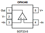
The OPA348 in the SOT-23-5 package has five pins. The table below describes each pin:

Pin Number Pin Name Description
1 V+ Positive power supply
2 IN- Inverting input
3 IN+ Non-inverting input
4 V- (GND) Negative power supply or ground
5 OUT Output of the operational amplifier

Usage Instructions

How to Use the OPA348 in a Circuit

  1. Power Supply: Connect the V+ pin to a positive voltage source (2.1 V to 5.5 V) and the V- pin to ground or a negative voltage source, depending on your design.
  2. Input Connections:
    • Connect the signal to be amplified to the IN+ or IN- pin, depending on whether you need non-inverting or inverting amplification.
    • Use appropriate resistors to set the gain if the op-amp is used in a feedback configuration.
  3. Output Connection: The amplified signal will be available at the OUT pin. Ensure the load connected to the output does not exceed the op-amp's drive capability.
  4. Bypass Capacitor: Place a 0.1 µF ceramic capacitor close to the V+ pin to stabilize the power supply and reduce noise.

Important Considerations

  • Input Voltage Range: Ensure the input signal stays within the specified common-mode voltage range to avoid distortion or malfunction.
  • Load Impedance: Use a load impedance of at least 10 kΩ for optimal performance.
  • Thermal Management: Although the OPA348 has low power consumption, ensure adequate ventilation if used in high-temperature environments.

Example: Connecting OPA348 to an Arduino UNO

The OPA348 can be used to amplify an analog signal before feeding it into the Arduino's analog input pins. Below is an example of a simple non-inverting amplifier circuit with Arduino code:

Circuit Diagram

  • Connect the OPA348's V+ pin to the Arduino's 5V pin.
  • Connect the V- pin to the Arduino's GND pin.
  • Connect the signal source to the IN+ pin.
  • Use a resistor divider network to set the gain (e.g., R1 = 10 kΩ, R2 = 100 kΩ).
  • Connect the OUT pin to one of the Arduino's analog input pins (e.g., A0).

Arduino Code

// Simple Arduino code to read the amplified signal from the OPA348
// and display the value on the serial monitor.

const int analogPin = A0; // Pin connected to the OPA348 output

void setup() {
  Serial.begin(9600); // Initialize serial communication at 9600 baud
}

void loop() {
  int sensorValue = analogRead(analogPin); // Read the analog value
  float voltage = sensorValue * (5.0 / 1023.0); // Convert to voltage
  Serial.print("Amplified Voltage: ");
  Serial.print(voltage);
  Serial.println(" V");
  delay(500); // Wait for 500 ms before the next reading
}

Troubleshooting and FAQs

Common Issues

  1. No Output Signal:

    • Check the power supply connections (V+ and V-).
    • Verify that the input signal is within the op-amp's input voltage range.
    • Ensure the feedback network is correctly configured.
  2. Distorted Output:

    • Confirm that the input signal is not exceeding the common-mode voltage range.
    • Check if the load impedance is too low for the op-amp to drive.
  3. High Noise Levels:

    • Add a bypass capacitor (0.1 µF) close to the V+ pin.
    • Use shielded cables for input and output connections.
  4. Overheating:

    • Ensure the supply voltage does not exceed the maximum rating.
    • Verify that the ambient temperature is within the operating range.

FAQs

Q1: Can the OPA348 operate with a single power supply?
Yes, the OPA348 is designed for single-supply operation and can function with a supply voltage as low as 2.1 V.

Q2: What is the maximum gain I can achieve with the OPA348?
The maximum gain depends on the feedback resistor configuration and the op-amp's bandwidth. For high gains, ensure the signal frequency is within the op-amp's gain-bandwidth product.

Q3: Is the OPA348 suitable for audio applications?
While the OPA348 can be used for low-frequency audio signals, its 1 MHz gain-bandwidth product may limit its performance in high-fidelity audio applications.

Q4: Can I use the OPA348 to drive capacitive loads?
Yes, but for large capacitive loads, consider adding a small resistor (e.g., 10 Ω) in series with the output to improve stability.