Cirkit Designer Logo
Cirkit Designer
Your all-in-one circuit design IDE
Home / 
Component Documentation

How to Use Level Shifter Breakout STEMMA QT Adafruit 5637: Examples, Pinouts, and Specs

Image of Level Shifter Breakout STEMMA QT Adafruit 5637
Cirkit Designer LogoDesign with Level Shifter Breakout STEMMA QT Adafruit 5637 in Cirkit Designer

Introduction

The Level Shifter Breakout STEMMA QT (Adafruit 5637) is a compact and versatile level shifter breakout board designed to facilitate communication between devices operating at different logic voltage levels. It is particularly useful for interfacing 3.3V logic devices with 5V logic devices, ensuring compatibility and reliable data transfer. The board features a bi-directional level shifting circuit and includes STEMMA QT connectors for easy plug-and-play integration.

Explore Projects Built with Level Shifter Breakout STEMMA QT Adafruit 5637

Use Cirkit Designer to design, explore, and prototype these projects online. Some projects support real-time simulation. Click "Open Project" to start designing instantly!
Arduino Mega 2560 Smart Home Automation System with LCD Display and Sensor Integration
Image of CPE_301_FINAL: A project utilizing Level Shifter Breakout STEMMA QT Adafruit 5637 in a practical application
This circuit is a multi-functional system controlled by an Arduino Mega 2560, featuring an LCD display, various LEDs, a stepper motor, a DC motor, and multiple sensors including a DHT11 humidity and temperature sensor and a water level sensor. The system also includes a real-time clock module for timekeeping and several pushbuttons for user interaction. The ULN2003A breakout board is used to drive the stepper motor, while the L293D motor driver controls the DC motor.
Cirkit Designer LogoOpen Project in Cirkit Designer
ESP32-Based Motion Tracking System with ICM20948 Sensor
Image of ICM20948: A project utilizing Level Shifter Breakout STEMMA QT Adafruit 5637 in a practical application
This circuit features a SparkFun ESP32 Thing Plus microcontroller interfaced with an Adafruit ICM20948 9-axis motion sensor via an Adafruit TXB0104 4-channel bi-directional level shifter. The ESP32 reads data from the ICM20948 sensor, calculates orientation angles such as pitch, roll, yaw, and azimuth, and outputs these values to the serial monitor. The level shifter ensures compatibility between the 3.3V logic levels of the ESP32 and the 1.8V logic levels required by the ICM20948.
Cirkit Designer LogoOpen Project in Cirkit Designer
Arduino Mega 2560 Controlled Motor System with I2C Communication and Hall Effect Sensing
Image of Uni1: A project utilizing Level Shifter Breakout STEMMA QT Adafruit 5637 in a practical application
This is a motor control system with feedback and sensor integration. It uses an Arduino Mega 2560 to control MD03 motor drivers for DC motors, receives position and speed feedback from HEDS encoders and Hall sensors, and measures distance with SR02 ultrasonic sensors. Logic level converters ensure compatibility between different voltage levels of the components.
Cirkit Designer LogoOpen Project in Cirkit Designer
Arduino Mega 2560-Based Smart Home Automation System with LCD Display and Sensor Integration
Image of CPE 301 Final: A project utilizing Level Shifter Breakout STEMMA QT Adafruit 5637 in a practical application
This circuit is a multi-functional system controlled by an Arduino Mega 2560, featuring an LCD display, various LEDs, pushbuttons, a rotary potentiometer, a DHT11 sensor, a DS1307 RTC module, a water level sensor, and motor control via an L293D driver and a ULN2003 driver for a stepper motor. The circuit is designed to read sensor data, display information, and control motors and LEDs based on user input and sensor readings.
Cirkit Designer LogoOpen Project in Cirkit Designer

Explore Projects Built with Level Shifter Breakout STEMMA QT Adafruit 5637

Use Cirkit Designer to design, explore, and prototype these projects online. Some projects support real-time simulation. Click "Open Project" to start designing instantly!
Image of CPE_301_FINAL: A project utilizing Level Shifter Breakout STEMMA QT Adafruit 5637 in a practical application
Arduino Mega 2560 Smart Home Automation System with LCD Display and Sensor Integration
This circuit is a multi-functional system controlled by an Arduino Mega 2560, featuring an LCD display, various LEDs, a stepper motor, a DC motor, and multiple sensors including a DHT11 humidity and temperature sensor and a water level sensor. The system also includes a real-time clock module for timekeeping and several pushbuttons for user interaction. The ULN2003A breakout board is used to drive the stepper motor, while the L293D motor driver controls the DC motor.
Cirkit Designer LogoOpen Project in Cirkit Designer
Image of ICM20948: A project utilizing Level Shifter Breakout STEMMA QT Adafruit 5637 in a practical application
ESP32-Based Motion Tracking System with ICM20948 Sensor
This circuit features a SparkFun ESP32 Thing Plus microcontroller interfaced with an Adafruit ICM20948 9-axis motion sensor via an Adafruit TXB0104 4-channel bi-directional level shifter. The ESP32 reads data from the ICM20948 sensor, calculates orientation angles such as pitch, roll, yaw, and azimuth, and outputs these values to the serial monitor. The level shifter ensures compatibility between the 3.3V logic levels of the ESP32 and the 1.8V logic levels required by the ICM20948.
Cirkit Designer LogoOpen Project in Cirkit Designer
Image of Uni1: A project utilizing Level Shifter Breakout STEMMA QT Adafruit 5637 in a practical application
Arduino Mega 2560 Controlled Motor System with I2C Communication and Hall Effect Sensing
This is a motor control system with feedback and sensor integration. It uses an Arduino Mega 2560 to control MD03 motor drivers for DC motors, receives position and speed feedback from HEDS encoders and Hall sensors, and measures distance with SR02 ultrasonic sensors. Logic level converters ensure compatibility between different voltage levels of the components.
Cirkit Designer LogoOpen Project in Cirkit Designer
Image of CPE 301 Final: A project utilizing Level Shifter Breakout STEMMA QT Adafruit 5637 in a practical application
Arduino Mega 2560-Based Smart Home Automation System with LCD Display and Sensor Integration
This circuit is a multi-functional system controlled by an Arduino Mega 2560, featuring an LCD display, various LEDs, pushbuttons, a rotary potentiometer, a DHT11 sensor, a DS1307 RTC module, a water level sensor, and motor control via an L293D driver and a ULN2003 driver for a stepper motor. The circuit is designed to read sensor data, display information, and control motors and LEDs based on user input and sensor readings.
Cirkit Designer LogoOpen Project in Cirkit Designer

Common Applications and Use Cases

  • Interfacing 3.3V microcontrollers (e.g., Raspberry Pi, ESP32) with 5V peripherals (e.g., sensors, displays).
  • Bridging communication between I2C devices operating at different voltage levels.
  • Prototyping and testing circuits with mixed voltage requirements.
  • Educational projects and hobbyist electronics.

Technical Specifications

Key Technical Details

  • Operating Voltage (High Side): 5V (typical)
  • Operating Voltage (Low Side): 3.3V (typical)
  • Logic Level Compatibility: 1.8V to 5V
  • Communication Protocols Supported: I2C, UART, SPI, GPIO
  • Connectors: STEMMA QT (Qwiic-compatible) for I2C
  • Dimensions: 25mm x 17mm x 4mm
  • Weight: ~1g

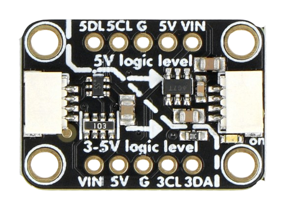
Pin Configuration and Descriptions

The Adafruit 5637 breakout board has the following pinout:

Pin Name Description
VIN Power input for the high-side voltage (typically 5V).
GND Ground connection.
LV Power input for the low-side voltage (typically 3.3V).
HV High-side voltage reference for level shifting (connect to VIN).
A1, A2, A3, A4 Low-side logic pins for bi-directional level shifting.
B1, B2, B3, B4 High-side logic pins corresponding to A1, A2, A3, and A4.
STEMMA QT IN I2C input connector for easy daisy-chaining with other STEMMA QT devices.
STEMMA QT OUT I2C output connector for chaining additional devices.

Usage Instructions

How to Use the Component in a Circuit

  1. Power Connections:

    • Connect the VIN pin to the high-side voltage source (e.g., 5V).
    • Connect the LV pin to the low-side voltage source (e.g., 3.3V).
    • Connect the GND pin to the ground of your circuit.
  2. Logic Connections:

    • Use the A1-A4 pins for the low-voltage side (e.g., 3.3V logic).
    • Use the corresponding B1-B4 pins for the high-voltage side (e.g., 5V logic).
    • For I2C communication, connect the SDA and SCL lines to any of the A or B pins as needed.
  3. STEMMA QT Integration:

    • Use the STEMMA QT connectors to easily integrate the breakout board into an I2C bus with other compatible devices.

Important Considerations and Best Practices

  • Ensure that the VIN and LV voltages are within the supported range (1.8V to 5V).
  • Always connect the GND pin to the common ground of your circuit to avoid communication issues.
  • For I2C applications, ensure proper pull-up resistors are present on the SDA and SCL lines if not already included in your setup.
  • Avoid exceeding the maximum current rating of the board to prevent damage.

Example: Using with Arduino UNO

Below is an example of how to use the Adafruit 5637 to interface a 3.3V sensor with a 5V Arduino UNO via I2C.

Circuit Connections

  • Connect VIN to the Arduino's 5V pin.
  • Connect LV to the sensor's 3.3V power pin.
  • Connect GND to the common ground.
  • Connect A1 to the sensor's SDA pin and B1 to the Arduino's SDA pin.
  • Connect A2 to the sensor's SCL pin and B2 to the Arduino's SCL pin.

Arduino Code Example

#include <Wire.h>

// I2C address of the 3.3V sensor
#define SENSOR_ADDRESS 0x40  

void setup() {
  Wire.begin(); // Initialize I2C communication
  Serial.begin(9600); // Start serial communication for debugging

  // Check if the sensor is connected
  Wire.beginTransmission(SENSOR_ADDRESS);
  if (Wire.endTransmission() == 0) {
    Serial.println("Sensor detected!");
  } else {
    Serial.println("Sensor not detected. Check connections.");
  }
}

void loop() {
  // Example: Read data from the sensor
  Wire.beginTransmission(SENSOR_ADDRESS);
  Wire.write(0x00); // Command to read data (depends on the sensor)
  Wire.endTransmission();

  Wire.requestFrom(SENSOR_ADDRESS, 2); // Request 2 bytes of data
  if (Wire.available() == 2) {
    int data = Wire.read() << 8 | Wire.read(); // Combine two bytes
    Serial.print("Sensor Data: ");
    Serial.println(data);
  }

  delay(1000); // Wait 1 second before the next read
}

Troubleshooting and FAQs

Common Issues and Solutions

  1. No Communication Between Devices:

    • Ensure that the GND pin is connected to the common ground of all devices.
    • Verify that the VIN and LV voltages are correctly supplied.
    • Check the wiring between the A and B pins for proper connections.
  2. I2C Devices Not Detected:

    • Confirm that the pull-up resistors are present on the SDA and SCL lines.
    • Use an I2C scanner sketch to verify the device address.
  3. Unstable or Intermittent Communication:

    • Ensure that the power supply is stable and within the specified voltage range.
    • Check for loose connections or damaged wires.

FAQs

Q: Can I use this board for SPI communication?
A: Yes, the Adafruit 5637 supports SPI communication. Connect the SPI lines (MOSI, MISO, SCK, CS) to the appropriate A and B pins.

Q: What is the maximum data rate supported?
A: The board supports data rates up to 400kHz for I2C and similar speeds for other protocols, depending on the circuit design.

Q: Can I daisy-chain multiple level shifters?
A: Yes, you can daisy-chain multiple level shifters using the STEMMA QT connectors for I2C communication.

Q: Is this board compatible with 1.8V logic?
A: Yes, the board supports logic levels as low as 1.8V on the low side. Ensure proper voltage is supplied to the LV pin.