Cirkit Designer Logo
Cirkit Designer
Your all-in-one circuit design IDE
Home / 
Component Documentation

How to Use L298N MOTOR DRIVER: Examples, Pinouts, and Specs

Image of L298N MOTOR DRIVER
Cirkit Designer LogoDesign with L298N MOTOR DRIVER in Cirkit Designer

Introduction

The L298N motor driver is a versatile dual H-bridge motor driver integrated circuit (IC) capable of controlling the speed and direction of two DC motors or one stepper motor. It is widely used in robotics, automation projects, and various applications where precise motor control is required.

Explore Projects Built with L298N MOTOR DRIVER

Use Cirkit Designer to design, explore, and prototype these projects online. Some projects support real-time simulation. Click "Open Project" to start designing instantly!
L298N DC Motor Driver Controlled DC Motor System
Image of 275 GC: A project utilizing L298N MOTOR DRIVER in a practical application
This circuit is designed to control a DC motor using an L298N motor driver module. The motor driver is powered by a DC power source and interfaces with the motor through its output pins, while resistors are used to manage the input signals to the driver.
Cirkit Designer LogoOpen Project in Cirkit Designer
ESP32-Controlled Dual Motor Driver for Robotic Vehicle
Image of ESP 32 BT BOT: A project utilizing L298N MOTOR DRIVER in a practical application
This circuit is designed to control four DC gearmotors using an L298N motor driver module, which is interfaced with an ESP32 microcontroller. The ESP32 uses its GPIO pins to send control signals to the L298N driver, enabling the independent operation of the motors, such as direction and speed control. Power is supplied by a 12V battery connected to the motor driver, with the ESP32 receiving its power through a voltage regulator on the L298N module.
Cirkit Designer LogoOpen Project in Cirkit Designer
Battery-Powered Line Following Robot with L298N Motor Driver and KY-033 Sensors
Image of obstacle-avoiding robot: A project utilizing L298N MOTOR DRIVER in a practical application
This circuit is designed to control a two-wheeled robot using an L298N motor driver, powered by two 18650 Li-ion batteries. It includes two KY-033 line tracking sensors for navigation and a 74HC04 inverter to process sensor signals and control the motor driver inputs.
Cirkit Designer LogoOpen Project in Cirkit Designer
ESP32 and L298N Motor Driver-Based Wi-Fi Controlled Robotic Car
Image of ESP 32 BT BOT: A project utilizing L298N MOTOR DRIVER in a practical application
This circuit is a motor control system using an ESP32 microcontroller and an L298N motor driver to control four DC gear motors. The ESP32 provides control signals to the L298N, which in turn drives the motors, powered by a 12V battery, enabling bidirectional control of the motors for applications such as a robotic vehicle.
Cirkit Designer LogoOpen Project in Cirkit Designer

Explore Projects Built with L298N MOTOR DRIVER

Use Cirkit Designer to design, explore, and prototype these projects online. Some projects support real-time simulation. Click "Open Project" to start designing instantly!
Image of 275 GC: A project utilizing L298N MOTOR DRIVER in a practical application
L298N DC Motor Driver Controlled DC Motor System
This circuit is designed to control a DC motor using an L298N motor driver module. The motor driver is powered by a DC power source and interfaces with the motor through its output pins, while resistors are used to manage the input signals to the driver.
Cirkit Designer LogoOpen Project in Cirkit Designer
Image of ESP 32 BT BOT: A project utilizing L298N MOTOR DRIVER in a practical application
ESP32-Controlled Dual Motor Driver for Robotic Vehicle
This circuit is designed to control four DC gearmotors using an L298N motor driver module, which is interfaced with an ESP32 microcontroller. The ESP32 uses its GPIO pins to send control signals to the L298N driver, enabling the independent operation of the motors, such as direction and speed control. Power is supplied by a 12V battery connected to the motor driver, with the ESP32 receiving its power through a voltage regulator on the L298N module.
Cirkit Designer LogoOpen Project in Cirkit Designer
Image of obstacle-avoiding robot: A project utilizing L298N MOTOR DRIVER in a practical application
Battery-Powered Line Following Robot with L298N Motor Driver and KY-033 Sensors
This circuit is designed to control a two-wheeled robot using an L298N motor driver, powered by two 18650 Li-ion batteries. It includes two KY-033 line tracking sensors for navigation and a 74HC04 inverter to process sensor signals and control the motor driver inputs.
Cirkit Designer LogoOpen Project in Cirkit Designer
Image of ESP 32 BT BOT: A project utilizing L298N MOTOR DRIVER in a practical application
ESP32 and L298N Motor Driver-Based Wi-Fi Controlled Robotic Car
This circuit is a motor control system using an ESP32 microcontroller and an L298N motor driver to control four DC gear motors. The ESP32 provides control signals to the L298N, which in turn drives the motors, powered by a 12V battery, enabling bidirectional control of the motors for applications such as a robotic vehicle.
Cirkit Designer LogoOpen Project in Cirkit Designer

Common Applications and Use Cases
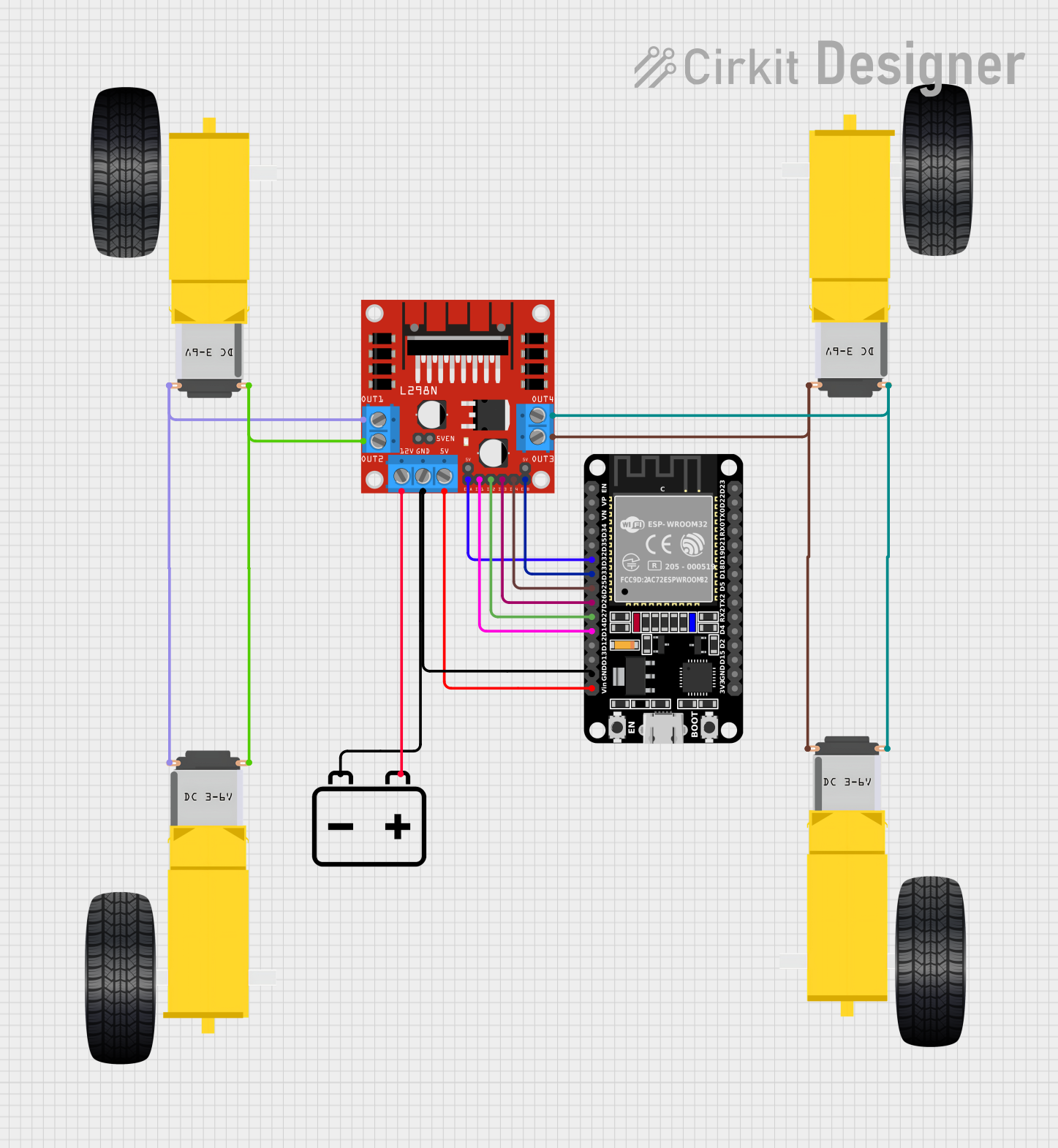
  • Robotics
  • CNC machines
  • Automated guided vehicles (AGVs)
  • Home automation systems
  • DIY electronic projects

Technical Specifications

Key Technical Details

  • Operating Voltage: 5V to 35V
  • Logic Voltage: 5V
  • Continuous Output Current: 2A per channel (3A peak)
  • Power Dissipation: 25W

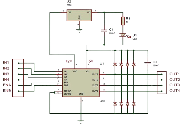
Pin Configuration and Descriptions

Pin Number Pin Name Description
1 OUT1 Motor A output 1
2 OUT2 Motor A output 2
3 VS Motor power supply (up to 35V)
4 GND Ground
5 OUT3 Motor B output 1
6 OUT4 Motor B output 2
7 VSS Logic power supply (5V)
8 ENA Enable motor A / PWM speed control for motor A
9 IN1 Input 1 for motor A direction control
10 IN2 Input 2 for motor A direction control
11 IN3 Input 3 for motor B direction control
12 IN4 Input 4 for motor B direction control
13 ENB Enable motor B / PWM speed control for motor B
14 CS Current sensing output (optional)

Usage Instructions

How to Use the Component in a Circuit

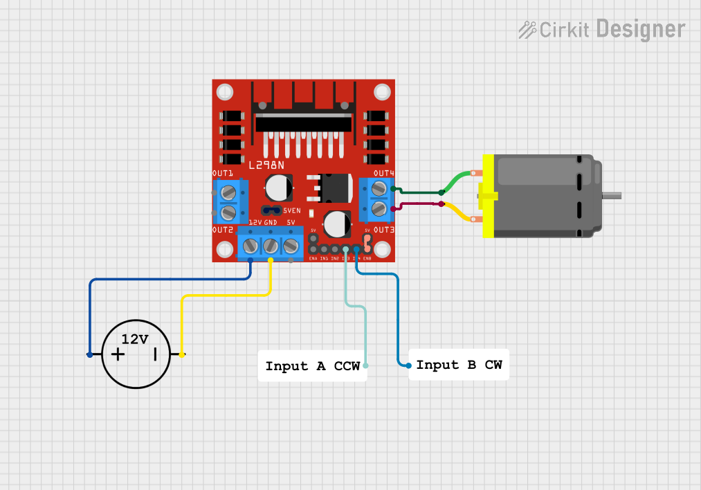
  1. Connect the motor power supply (VS) to the motors' voltage source, ensuring it does not exceed 35V.
  2. Connect the logic power supply (VSS) to a 5V source.
  3. Connect the ground pin (GND) to the common ground of the power supplies.
  4. Connect the motors to the OUT1/OUT2 and OUT3/OUT4 for motor A and B, respectively.
  5. Use the ENA and ENB pins to enable the motors and control their speed using PWM signals.
  6. Control the direction of the motors by setting the IN1/IN2 and IN3/IN4 pins to high or low.

Important Considerations and Best Practices

  • Always use a separate power supply for the motors to prevent noise and voltage drops on the logic side.
  • Use heat sinks if operating near the maximum current rating to prevent overheating.
  • Ensure that the power supply can handle the motors' current requirements.
  • Use flyback diodes if necessary to protect against voltage spikes when the motors turn off.

Example Connection to an Arduino UNO

// Define the L298N control pins
const int enA = 9;
const int in1 = 8;
const int in2 = 7;
const int enB = 3;
const int in3 = 5;
const int in4 = 4;

void setup() {
  // Set all the motor control pins to outputs
  pinMode(enA, OUTPUT);
  pinMode(enB, OUTPUT);
  pinMode(in1, OUTPUT);
  pinMode(in2, OUTPUT);
  pinMode(in3, OUTPUT);
  pinMode(in4, OUTPUT);
}

void loop() {
  // Turn on motor A & B
  digitalWrite(in1, HIGH);
  digitalWrite(in2, LOW);
  digitalWrite(in3, HIGH);
  digitalWrite(in4, LOW);
  
  // Set speed to 200 out of possible range 0-255
  analogWrite(enA, 200);
  analogWrite(enB, 200);
  
  // Wait 2 seconds
  delay(2000);
  
  // Change motor directions
  digitalWrite(in1, LOW);
  digitalWrite(in2, HIGH);
  digitalWrite(in3, LOW);
  digitalWrite(in4, HIGH);
  
  // Wait 2 seconds
  delay(2000);
  
  // Turn off motors
  digitalWrite(enA, LOW);
  digitalWrite(enB, LOW);
}

Troubleshooting and FAQs

Common Issues Users Might Face

  • Motor not running: Check power supply connections, ensure the enable pins (ENA/ENB) are set to high, and verify that the input pins (IN1-IN4) are correctly configured.
  • Overheating: Ensure proper heat sinking and that the current does not exceed the rated specifications.
  • Inconsistent motor speed: Check for PWM signal integrity and ensure a stable power supply.

Solutions and Tips for Troubleshooting

  • Use a multimeter to check for proper voltage levels at the power supply and the motor outputs.
  • If using PWM for speed control, ensure the PWM frequency is within the acceptable range for the L298N.
  • Double-check wiring, especially the ground connections, to ensure they are secure and have a good connection.

FAQs

Q: Can I control a stepper motor with the L298N? A: Yes, the L298N can control a bipolar stepper motor by using the two H-bridges to control the two coils.

Q: What is the maximum current the L298N can handle? A: The L298N can handle up to 2A per channel continuously, with peak currents of 3A.

Q: Do I need to use external diodes with the L298N? A: The L298N has built-in diodes for back EMF protection. However, additional external diodes may be used for extra protection.

Q: How do I use the current sensing feature? A: The CS pin can be connected to an analog input on a microcontroller to measure the voltage proportional to the motor current.