How to Use Push button: Examples, Pinouts, and Specs
Introduction
The UTBM PushButton1 is a momentary switch designed to complete an electrical circuit when pressed. It is commonly used as a user input device to control various electronic functions or devices. When the button is released, the circuit is broken, making it ideal for applications requiring temporary activation.
Explore Projects Built with Push button


Explore Projects Built with Push button
Common Applications
- User input for microcontroller-based projects (e.g., Arduino, Raspberry Pi)
- Reset or power buttons in electronic devices
- Control panels for appliances and machinery
- Prototyping and testing circuits
- Triggering events in automation systems
Technical Specifications
The following table outlines the key technical details of the UTBM PushButton1:
| Parameter | Specification |
|---|---|
| Manufacturer | UTBM |
| Part ID | PushButton1 |
| Type | Momentary switch |
| Contact Configuration | SPST (Single Pole Single Throw) |
| Operating Voltage | 3.3V to 12V |
| Maximum Current Rating | 50mA |
| Contact Resistance | ≤ 50 mΩ |
| Insulation Resistance | ≥ 100 MΩ |
| Operating Temperature | -20°C to +70°C |
| Mechanical Lifespan | 100,000 cycles |
Pin Configuration and Descriptions
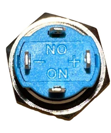
The UTBM PushButton1 has four pins, typically arranged in a square configuration. The following table describes the pin functionality:
| Pin Number | Description |
|---|---|
| 1 | Terminal 1 of the switch |
| 2 | Terminal 2 of the switch |
| 3 | Terminal 1 (internally connected to Pin 1) |
| 4 | Terminal 2 (internally connected to Pin 2) |
Note: Pins 1 and 3 are internally connected, as are Pins 2 and 4. This allows for flexible placement in a circuit.
Usage Instructions
How to Use the Push Button in a Circuit
- Identify the Pins: Determine which pins are connected internally (Pins 1 & 3, and Pins 2 & 4).
- Connect to Circuit:
- Connect one pair of pins (e.g., Pins 1 and 3) to the input signal or power source.
- Connect the other pair (e.g., Pins 2 and 4) to the load or microcontroller input.
- Debounce the Button: Use a resistor-capacitor (RC) circuit or software debounce logic to prevent false triggering caused by mechanical bouncing.
- Test the Circuit: Press the button to ensure it completes the circuit and triggers the desired action.
Important Considerations and Best Practices
- Debouncing: Mechanical switches like push buttons can produce noise or multiple signals when pressed. Always implement hardware or software debouncing to ensure reliable operation.
- Current Limiting: Ensure the current through the button does not exceed the maximum rating of 50mA to avoid damage.
- Pull-Up or Pull-Down Resistors: When interfacing with microcontrollers, use pull-up or pull-down resistors to define the default state of the input pin.
- Mounting: Secure the button properly to avoid accidental disconnections or damage during use.
Example: Connecting to an Arduino UNO
Below is an example of how to connect the UTBM PushButton1 to an Arduino UNO and read its state:
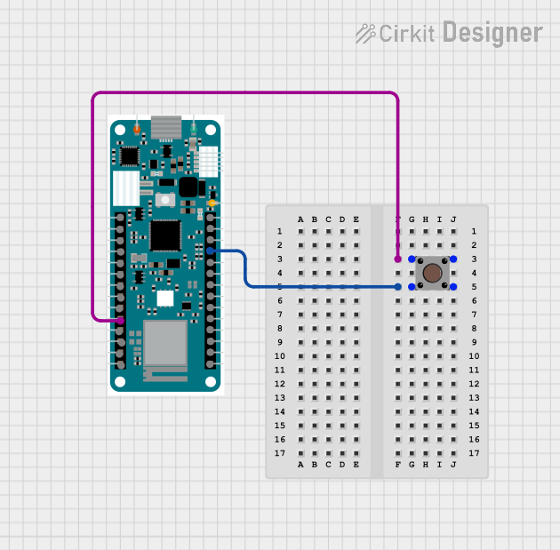
Circuit Diagram
- Connect one terminal of the push button to digital pin 2 on the Arduino.
- Connect the other terminal to ground.
- Use the Arduino's internal pull-up resistor to define the default state.
Arduino Code
// Define the pin connected to the push button
const int buttonPin = 2;

// Variable to store the button state
int buttonState = 0;

void setup() {
  // Set the button pin as input with an internal pull-up resistor
  pinMode(buttonPin, INPUT_PULLUP);

  // Initialize serial communication for debugging
  Serial.begin(9600);
}

void loop() {
  // Read the state of the push button
  buttonState = digitalRead(buttonPin);

  // Print the button state to the Serial Monitor
  if (buttonState == LOW) {
    // Button is pressed (LOW because of pull-up resistor)
    Serial.println("Button Pressed");
  } else {
    // Button is not pressed
    Serial.println("Button Released");
  }

  // Add a small delay to avoid spamming the Serial Monitor
  delay(100);
}
Note: The internal pull-up resistor ensures the pin reads HIGH when the button is not pressed.
Troubleshooting and FAQs
Common Issues and Solutions
Button Not Responding:
- Cause: Incorrect wiring or loose connections.
- Solution: Double-check the wiring and ensure all connections are secure.
Button Triggers Multiple Times:
- Cause: Mechanical bouncing of the button.
- Solution: Implement hardware (RC circuit) or software debounce logic.
Microcontroller Not Detecting Button Press:
- Cause: Missing pull-up or pull-down resistor.
- Solution: Use an internal or external pull-up/pull-down resistor to define the default state.
Button Feels Stiff or Unresponsive:
- Cause: Dirt or wear inside the button.
- Solution: Clean the button or replace it if the mechanical lifespan is exceeded.
FAQs
Q1: Can I use the UTBM PushButton1 with a 5V system?
A1: Yes, the button is compatible with systems operating between 3.3V and 12V, including 5V systems.
Q2: Do I need an external resistor for the button?
A2: If you are using a microcontroller with internal pull-up or pull-down resistors (e.g., Arduino), you do not need an external resistor. Otherwise, you should add one.
Q3: How do I debounce the button in software?
A3: You can use a delay or a state-change detection algorithm in your code to filter out noise caused by mechanical bouncing.
Q4: Can the button handle AC signals?
A4: The button is designed for low-voltage DC applications. Using it with AC signals is not recommended.
By following this documentation, you can effectively integrate the UTBM PushButton1 into your projects and troubleshoot any issues that arise.