
How to Use TDs sensor: Examples, Pinouts, and Specs
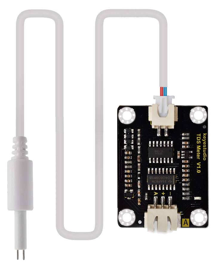
 Design with TDs sensor in Cirkit Designer
Introduction
A TDs (Total Dissolved Solids) sensor measures the concentration of dissolved solids in a liquid, typically expressed in parts per million (ppm). It is widely used in water quality monitoring and treatment applications to assess the purity of water. This sensor is essential in industries such as agriculture, aquaculture, hydroponics, and environmental monitoring, where maintaining water quality is critical.
Common applications include:
- Monitoring drinking water quality
- Measuring nutrient levels in hydroponic systems
- Testing water in aquariums and fish tanks
- Industrial water treatment systems
- Environmental water testing (e.g., rivers, lakes, and reservoirs)
Explore Projects Built with TDs sensor
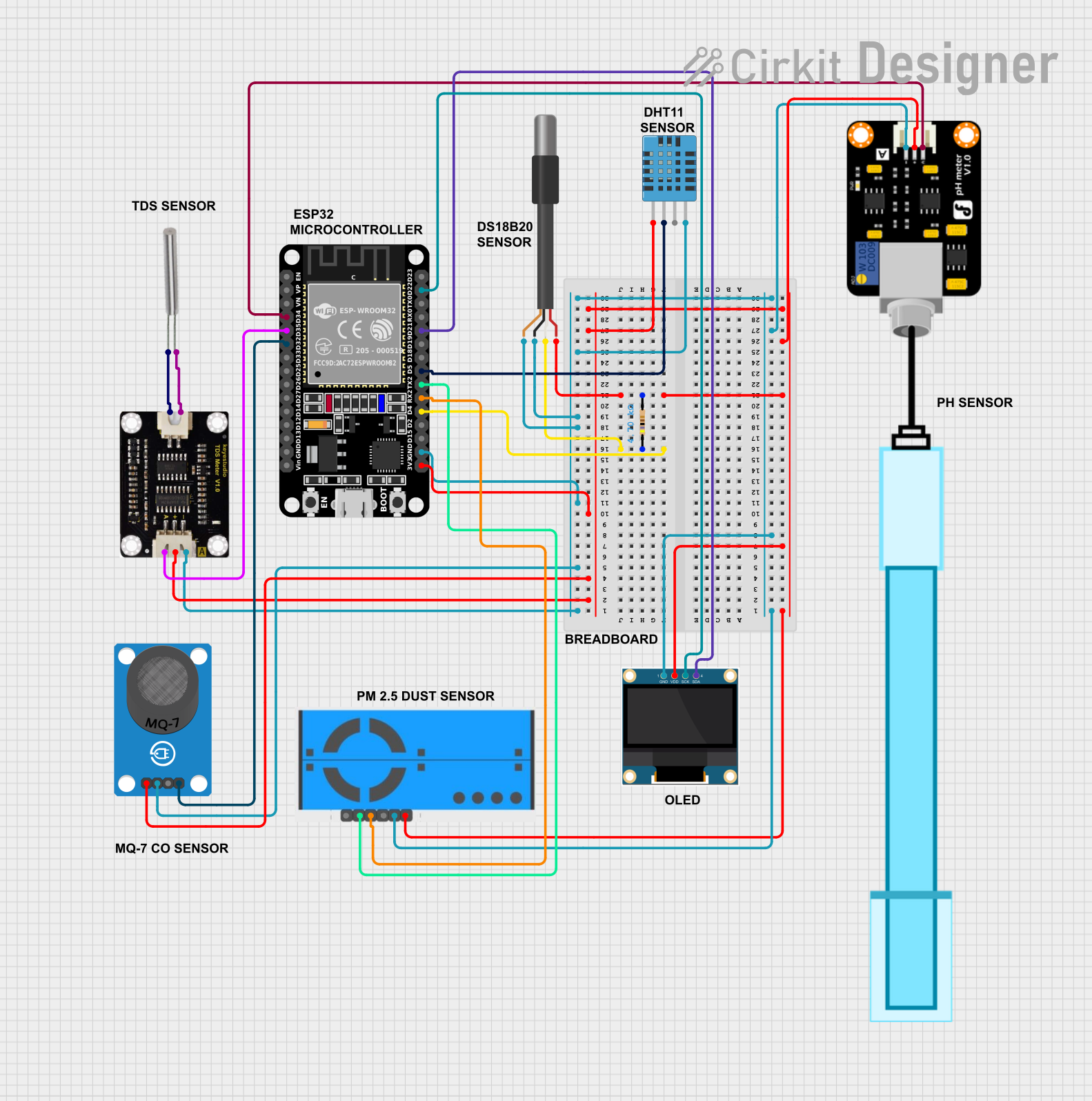 Open Project in Cirkit Designer
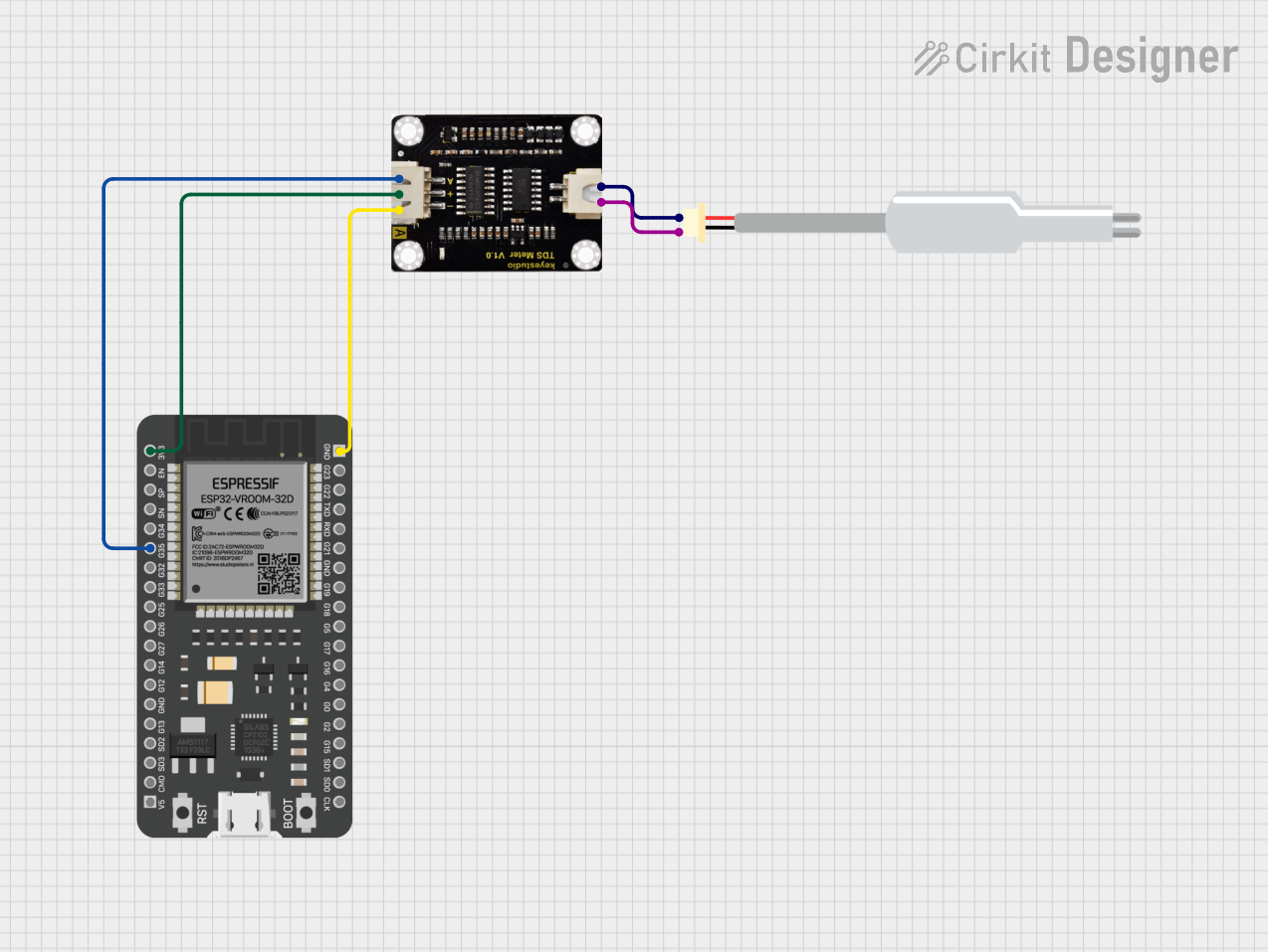 Open Project in Cirkit Designer
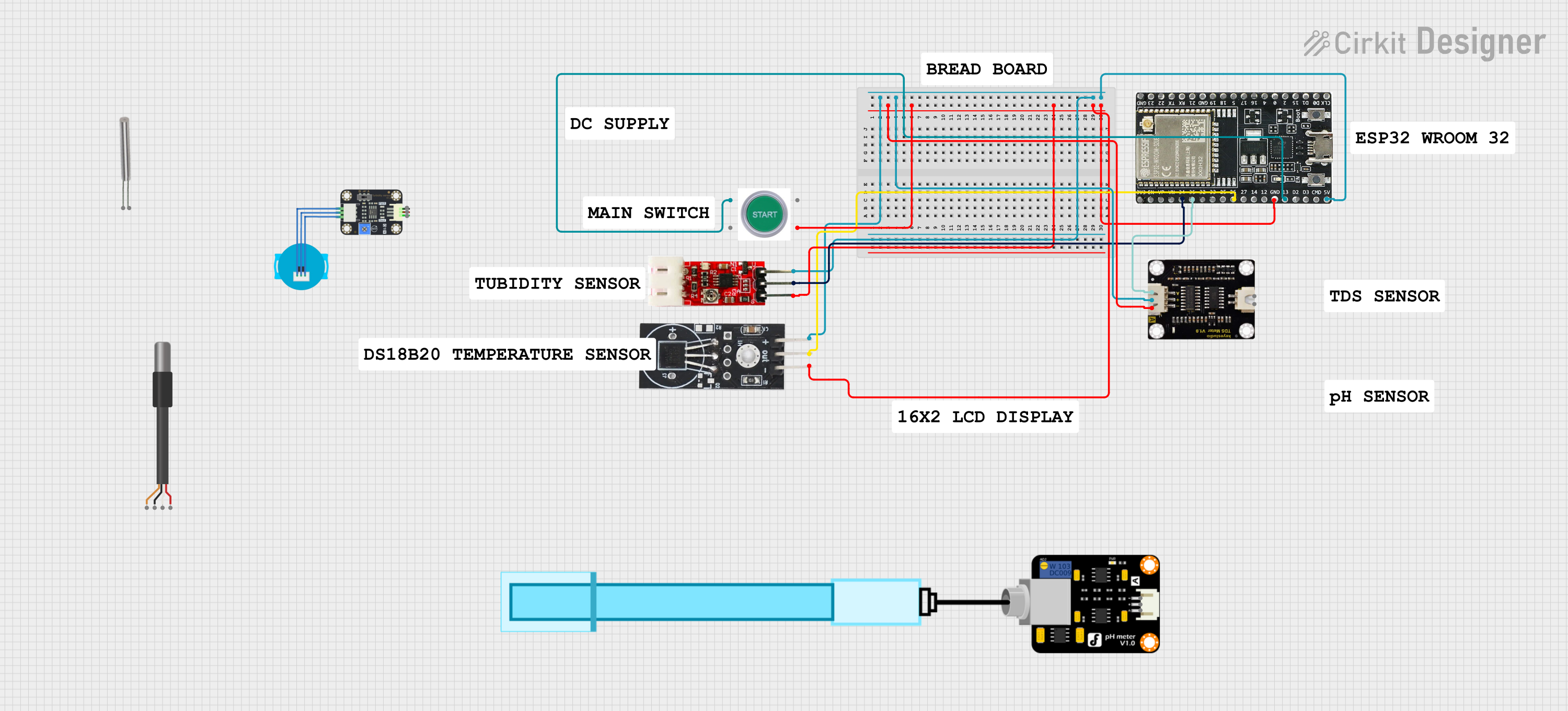 Open Project in Cirkit Designer
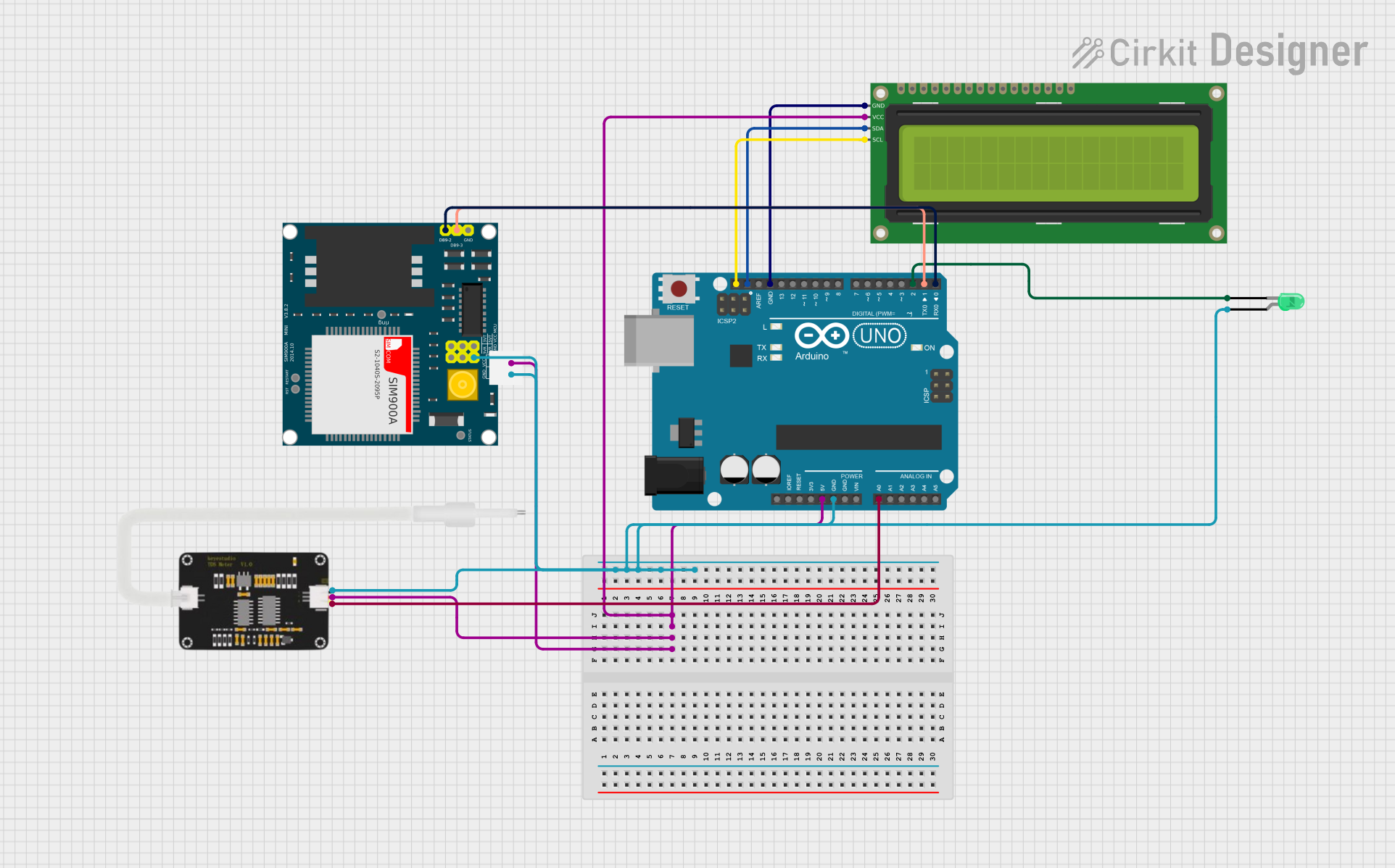 Open Project in Cirkit Designer
Explore Projects Built with TDs sensor
Open Project in Cirkit DesignerOpen Project in Cirkit DesignerOpen Project in Cirkit DesignerOpen Project in Cirkit DesignerTechnical Specifications
Below are the key technical details of a typical TDs sensor:
| Parameter | Value |
|---|---|
| Operating Voltage | 3.3V - 5V |
| Output Signal | Analog voltage (0-2.3V typical) |
| Measurement Range | 0 - 1000 ppm |
| Accuracy | ±10% (varies by sensor model) |
| Operating Temperature | 0°C - 60°C |
| Probe Material | Stainless steel |
| Cable Length | ~1 meter |
Pin Configuration
The TDs sensor module typically has the following pin configuration:
| Pin Name | Description |
|---|---|
| VCC | Power supply input (3.3V - 5V) |
| GND | Ground connection |
| AOUT | Analog output signal (proportional to TDs) |
Usage Instructions
How to Use the TDs Sensor in a Circuit
Connect the Sensor to a Microcontroller:
- Connect the
VCCpin of the sensor module to the 5V (or 3.3V) pin of your microcontroller. - Connect the
GNDpin to the ground (GND) of your microcontroller. - Connect the
AOUTpin to an analog input pin (e.g., A0) on your microcontroller.
- Connect the
Calibrate the Sensor:
- Before using the sensor, calibrate it using a known TDs solution to ensure accurate readings.
- Adjust the potentiometer on the module (if available) to fine-tune the output.
Place the Probe in the Liquid:
- Submerge the stainless steel probe in the liquid to be tested. Ensure the probe is fully immersed but avoid submerging the module itself.
Read the Analog Signal:
- The sensor outputs an analog voltage proportional to the TDs value. Use an analog-to-digital converter (ADC) on your microcontroller to read the signal.
Important Considerations and Best Practices
- Avoid Corrosion: Clean the probe regularly to prevent buildup of contaminants that can affect accuracy.
- Temperature Compensation: TDs readings can vary with temperature. Use a temperature sensor for compensation if precise measurements are required.
- Avoid Immersing the Module: Only the probe is waterproof; the module should remain dry.
- Power Supply: Ensure a stable power supply to avoid fluctuations in readings.
Example Code for Arduino UNO
Below is an example of how to use a TDs sensor with an Arduino UNO:
// Include necessary libraries
const int tdsPin = A0;  // Analog pin connected to the TDs sensor
float voltage;          // Variable to store the sensor's output voltage
float tdsValue;         // Variable to store the calculated TDs value

void setup() {
  Serial.begin(9600);   // Initialize serial communication at 9600 baud
  pinMode(tdsPin, INPUT); // Set the TDs pin as input
}

void loop() {
  int sensorValue = analogRead(tdsPin); // Read the analog value from the sensor
  voltage = sensorValue * (5.0 / 1023.0); // Convert ADC value to voltage
  tdsValue = (voltage * 1000) / 2.3; // Convert voltage to TDs (ppm)

  // Print the TDs value to the Serial Monitor
  Serial.print("TDs Value: ");
  Serial.print(tdsValue);
  Serial.println(" ppm");

  delay(1000); // Wait for 1 second before the next reading
}
Note: The formula for converting voltage to TDs value may vary depending on the specific sensor model. Refer to the sensor's datasheet for accurate calculations.
Troubleshooting and FAQs
Common Issues and Solutions
Inaccurate Readings:
- Cause: Probe contamination or improper calibration.
- Solution: Clean the probe with distilled water and recalibrate using a standard TDs solution.
No Output Signal:
- Cause: Loose or incorrect wiring.
- Solution: Double-check all connections and ensure the module is powered correctly.
Fluctuating Readings:
- Cause: Unstable power supply or electrical noise.
- Solution: Use a decoupling capacitor near the sensor module and ensure a stable power source.
Sensor Not Responding:
- Cause: Damaged probe or module.
- Solution: Inspect the probe and module for physical damage. Replace if necessary.
FAQs
Q: Can the TDs sensor measure salinity?
A: While the TDs sensor is not specifically designed for salinity measurement, it can provide an approximate indication of salinity since dissolved salts contribute to the TDs value.
Q: How often should I calibrate the sensor?
A: Calibration frequency depends on usage. For critical applications, calibrate before each use. For general use, calibrate monthly or as needed.
Q: Can I use the TDs sensor in hot liquids?
A: No, the sensor is designed for use in liquids with temperatures between 0°C and 60°C. Exceeding this range may damage the probe.
Q: Is the TDs sensor suitable for measuring drinking water?
A: Yes, the TDs sensor is commonly used to monitor drinking water quality. However, ensure the sensor is properly calibrated for accurate results.