Cirkit Designer Logo
Cirkit Designer
Your all-in-one circuit design IDE
Home / 
Component Documentation

How to Use ESP32-POE-ISO: Examples, Pinouts, and Specs

Image of ESP32-POE-ISO
Cirkit Designer LogoDesign with ESP32-POE-ISO in Cirkit Designer

Introduction

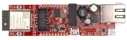
The ESP32-POE-ISO is a high-performance Wi-Fi and Bluetooth module designed by Olimex that integrates Ethernet connectivity with Power-over-Ethernet (PoE) support. It is based on the popular ESP32 chipset and features galvanic isolation on the Ethernet port, enhancing its suitability for industrial applications where reliable communication and power delivery are critical. This module is ideal for smart home devices, IoT applications, and professional automation systems.

Explore Projects Built with ESP32-POE-ISO

Use Cirkit Designer to design, explore, and prototype these projects online. Some projects support real-time simulation. Click "Open Project" to start designing instantly!
ESP32-POE-ISO Wi-Fi Controlled 4-Channel Relay Module
Image of ESP32-POE-ISO 4Channel Relay: A project utilizing ESP32-POE-ISO in a practical application
This circuit features an ESP32-POE-ISO microcontroller connected to a 4-channel 30A 5V relay module. The ESP32 controls the relay channels via its GPIO pins, allowing for the switching of high-power devices through the relay module.
Cirkit Designer LogoOpen Project in Cirkit Designer
ESP32-Powered 8-Channel Relay Controller with Wi-Fi Connectivity
Image of Olimex ESP32-POE2 4Ch X 2 Switches: A project utilizing ESP32-POE-ISO in a practical application
This circuit features an ESP32 microcontroller connected to an 8-channel relay module. The ESP32 controls the relay channels via its GPIO pins, allowing for the switching of external devices or loads through the relays.
Cirkit Designer LogoOpen Project in Cirkit Designer
ESP32-Powered Wi-Fi Controlled 8-Channel Relay Module
Image of Olimex ESP32-POE2 8Ch Switch and Sensors: A project utilizing ESP32-POE-ISO in a practical application
This circuit features an ESP32 microcontroller connected to an 8-channel relay module. The ESP32 controls the relay channels via its GPIO pins, allowing it to switch multiple external devices on and off. The ESP32 also provides power to the relay module.
Cirkit Designer LogoOpen Project in Cirkit Designer
ESP32-Based Wi-Fi Controlled 24V Input/Output Interface Module
Image of ESP32 4 på rad: A project utilizing ESP32-POE-ISO in a practical application
This circuit uses an ESP32 microcontroller to interface with a 3.3V PNP to 24V NPN photoelectric isolation module, which in turn connects to a 40-pin connector for general-purpose input and output. The 24V power supply provides the necessary voltage for the isolation module and the 40-pin connector, enabling the ESP32 to control and monitor high-voltage signals safely.
Cirkit Designer LogoOpen Project in Cirkit Designer

Explore Projects Built with ESP32-POE-ISO

Use Cirkit Designer to design, explore, and prototype these projects online. Some projects support real-time simulation. Click "Open Project" to start designing instantly!
Image of ESP32-POE-ISO 4Channel Relay: A project utilizing ESP32-POE-ISO in a practical application
ESP32-POE-ISO Wi-Fi Controlled 4-Channel Relay Module
This circuit features an ESP32-POE-ISO microcontroller connected to a 4-channel 30A 5V relay module. The ESP32 controls the relay channels via its GPIO pins, allowing for the switching of high-power devices through the relay module.
Cirkit Designer LogoOpen Project in Cirkit Designer
Image of Olimex ESP32-POE2 4Ch X 2 Switches: A project utilizing ESP32-POE-ISO in a practical application
ESP32-Powered 8-Channel Relay Controller with Wi-Fi Connectivity
This circuit features an ESP32 microcontroller connected to an 8-channel relay module. The ESP32 controls the relay channels via its GPIO pins, allowing for the switching of external devices or loads through the relays.
Cirkit Designer LogoOpen Project in Cirkit Designer
Image of Olimex ESP32-POE2 8Ch Switch and Sensors: A project utilizing ESP32-POE-ISO in a practical application
ESP32-Powered Wi-Fi Controlled 8-Channel Relay Module
This circuit features an ESP32 microcontroller connected to an 8-channel relay module. The ESP32 controls the relay channels via its GPIO pins, allowing it to switch multiple external devices on and off. The ESP32 also provides power to the relay module.
Cirkit Designer LogoOpen Project in Cirkit Designer
Image of ESP32 4 på rad: A project utilizing ESP32-POE-ISO in a practical application
ESP32-Based Wi-Fi Controlled 24V Input/Output Interface Module
This circuit uses an ESP32 microcontroller to interface with a 3.3V PNP to 24V NPN photoelectric isolation module, which in turn connects to a 40-pin connector for general-purpose input and output. The 24V power supply provides the necessary voltage for the isolation module and the 40-pin connector, enabling the ESP32 to control and monitor high-voltage signals safely.
Cirkit Designer LogoOpen Project in Cirkit Designer

Technical Specifications

Key Features

  • Wi-Fi 802.11 b/g/n
  • Bluetooth v4.2 BR/EDR and BLE
  • Integrated 10/100 Ethernet PHY
  • Power-over-Ethernet (IEEE 802.3af) compliant
  • Galvanic isolation on the Ethernet port
  • Operating Voltage: 5V via micro USB or PoE
  • Operating Temperature: -40°C to +85°C

Pin Configuration

Pin Number Name Description
1 GND Ground
2 3V3 3.3V Output
3 EN Enable
4 IO0 GPIO0
... ... ...
n VIN Input Voltage for PoE

Note: This is a simplified representation. Please refer to the Olimex ESP32-POE-ISO datasheet for the complete pinout and detailed descriptions.

Usage Instructions

Integration into a Circuit

To use the ESP32-POE-ISO in a circuit:

  1. Connect the GND pin to the ground of your power supply.
  2. Apply 5V to the VIN pin if not using PoE, or connect an Ethernet cable with PoE to the RJ45 connector.
  3. Use the IO pins to interface with sensors, actuators, or other peripherals as required by your application.

Best Practices

  • Ensure that the power supply is stable and within the specified voltage range.
  • When using PoE, verify that your Ethernet switch or injector is IEEE 802.3af compliant.
  • Avoid exposing the module to temperatures outside the specified operating range.
  • Use proper ESD precautions when handling the module to prevent damage.

Example Code for Arduino UNO

#include <WiFi.h>

// Replace with your network credentials
const char* ssid = "your_SSID";
const char* password = "your_PASSWORD";

void setup() {
  Serial.begin(115200);

  // Connect to Wi-Fi
  WiFi.begin(ssid, password);
  while (WiFi.status() != WL_CONNECTED) {
    delay(500);
    Serial.println("Connecting to WiFi...");
  }
  Serial.println("Connected to WiFi");
}

void loop() {
  // Put your main code here, to run repeatedly:
}

Note: The ESP32-POE-ISO is not directly compatible with an Arduino UNO but can be programmed using the Arduino IDE. The above code is for connecting the ESP32-POE-ISO to a Wi-Fi network.

Troubleshooting and FAQs

Common Issues

  • No Power: Ensure that the power supply or PoE source is correctly connected and within the specified voltage range.
  • Cannot Connect to Wi-Fi: Verify that the SSID and password are correct and that the Wi-Fi network is within range.
  • No Ethernet Connection: Check the Ethernet cable and ensure that the network switch supports PoE and is IEEE 802.3af compliant.

FAQs

Q: Can the ESP32-POE-ISO be used without an Ethernet connection?
A: Yes, it can operate solely on Wi-Fi or Bluetooth if Ethernet is not required.

Q: Is the module compatible with all PoE standards?
A: The ESP32-POE-ISO is compliant with the IEEE 802.3af standard. It may not be compatible with other PoE standards.

Q: Can I program the ESP32-POE-ISO using the Arduino IDE?
A: Yes, the module can be programmed using the Arduino IDE by selecting the appropriate ESP32 board from the board manager.

For further assistance, consult the Olimex ESP32-POE-ISO datasheet and the ESP32 forums for community support.