How to Use 4-digit FND: Examples, Pinouts, and Specs
Introduction
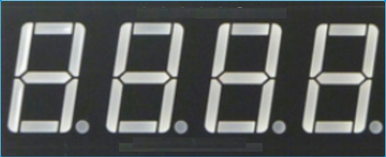
The JJY 3461 is a 4-digit seven-segment display designed to visually represent numerical data. Each digit consists of seven individual LED segments (labeled A-G) and a decimal point (DP), which can be illuminated to form numbers 0-9 and some letters. This component is widely used in digital clocks, counters, measurement devices, and other applications requiring numeric or alphanumeric displays.
Explore Projects Built with 4-digit FND

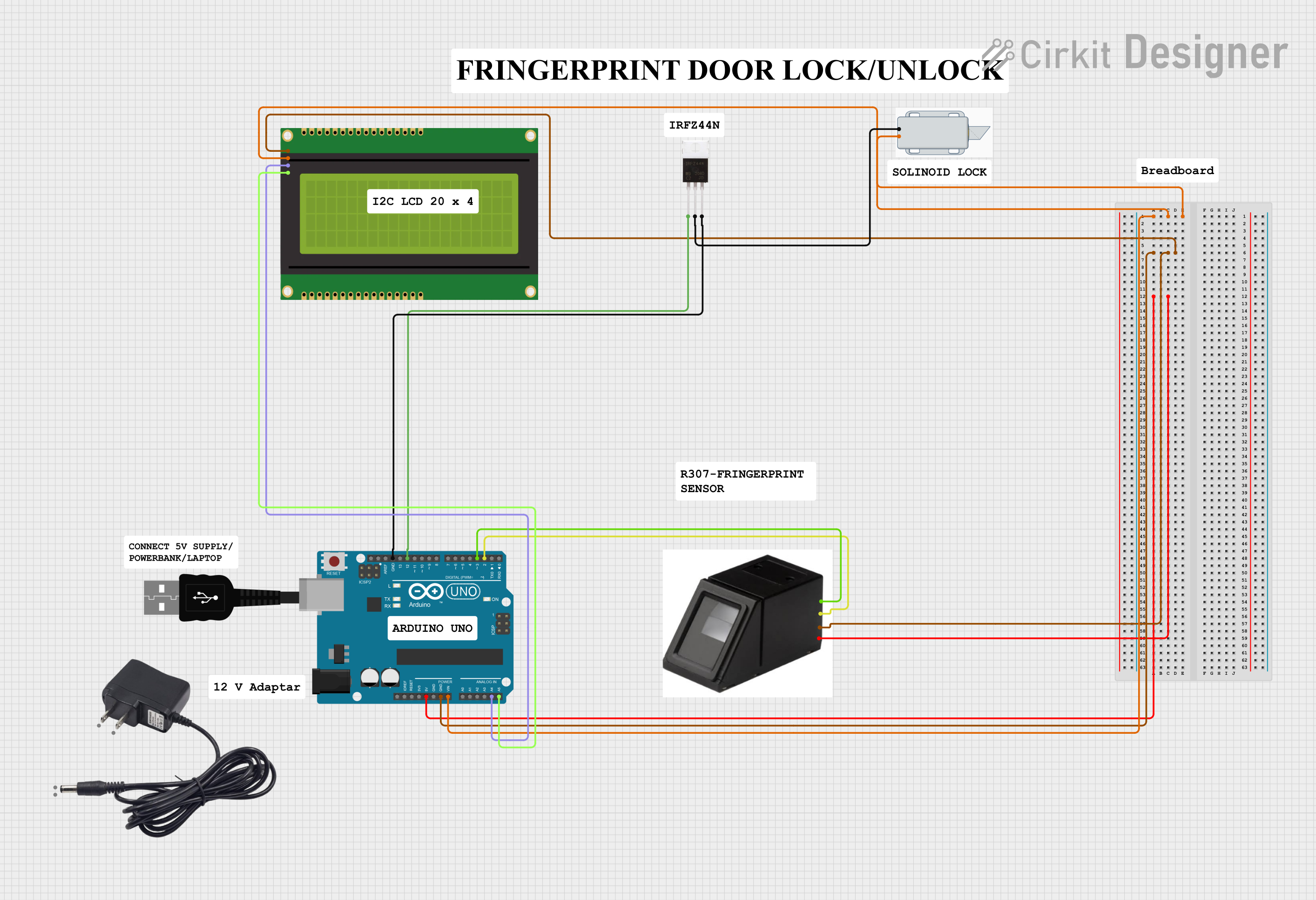
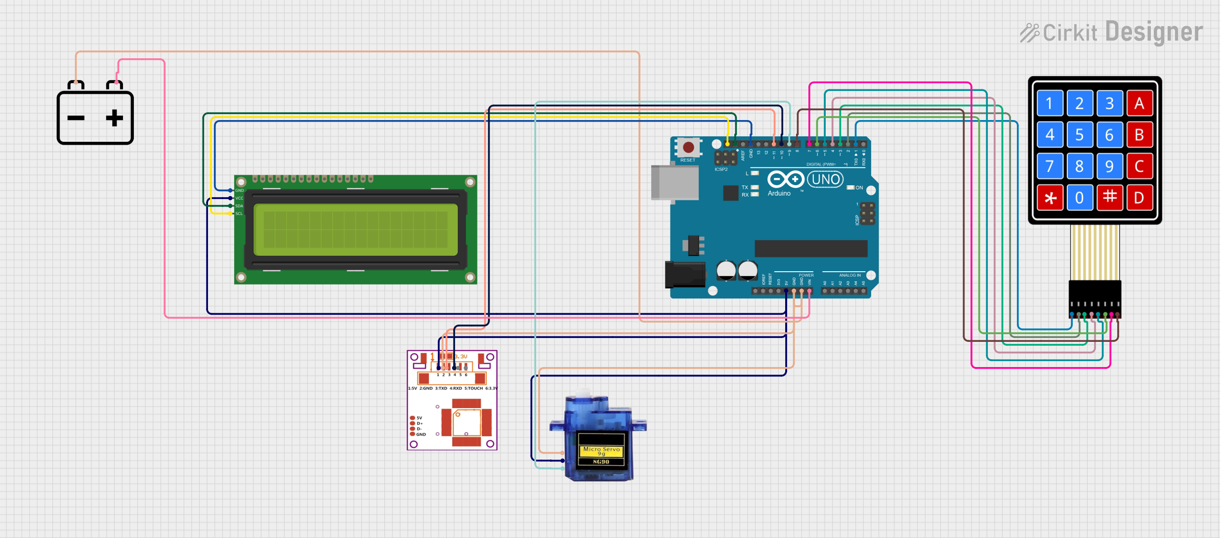
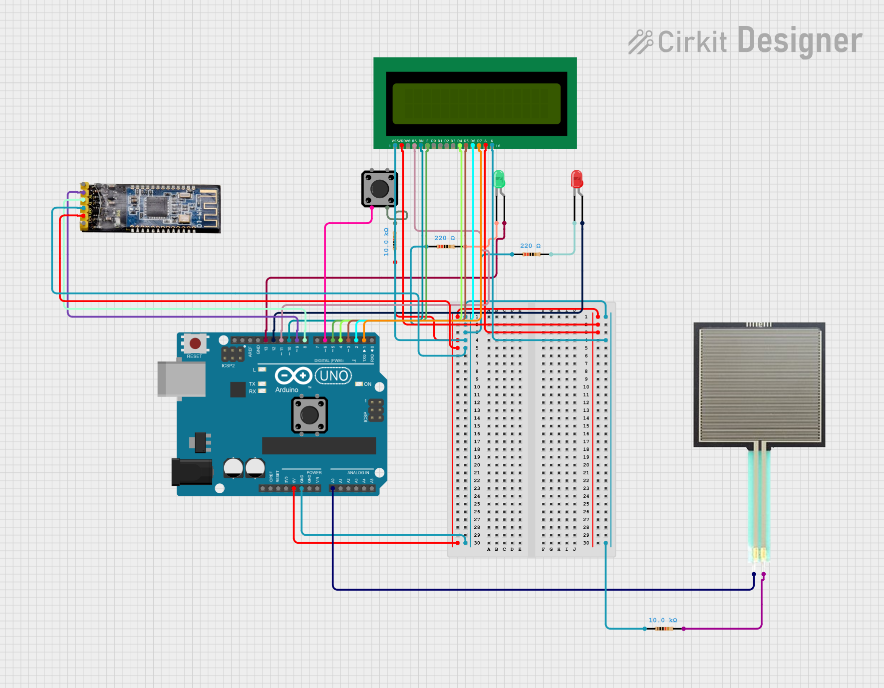
Explore Projects Built with 4-digit FND
Common Applications
- Digital clocks and timers
- Electronic counters
- Voltage, current, or temperature measurement devices
- Consumer electronics with numeric displays
Technical Specifications
The JJY 3461 is a versatile and efficient display module. Below are its key technical details:
General Specifications
| Parameter | Value |
|---|---|
| Manufacturer | JJY |
| Part ID | 3461 |
| Display Type | 4-digit seven-segment |
| Segment Type | LED (Light Emitting Diode) |
| Common Configuration | Common Cathode or Anode* |
| Operating Voltage (Vf) | 2.0V (typical per segment) |
| Forward Current (If) | 20mA (typical per segment) |
| Peak Forward Current | 100mA (max, duty cycle ≤10%) |
| Operating Temperature | -40°C to +85°C |
| Dimensions | 50mm x 19mm x 8mm |
* Ensure you verify the specific configuration (common cathode or anode) before use.
Pin Configuration
The JJY 3461 has 12 pins, with each pin connected to specific segments or digit controls. Below is the pinout for the common cathode version:
| Pin Number | Function | Description |
|---|---|---|
| 1 | Digit 1 Cathode (D1) | Controls the first digit |
| 2 | Segment E | Lights up segment E |
| 3 | Segment D | Lights up segment D |
| 4 | Digit 2 Cathode (D2) | Controls the second digit |
| 5 | Segment C | Lights up segment C |
| 6 | Segment DP | Lights up the decimal point |
| 7 | Segment B | Lights up segment B |
| 8 | Segment A | Lights up segment A |
| 9 | Digit 3 Cathode (D3) | Controls the third digit |
| 10 | Segment F | Lights up segment F |
| 11 | Segment G | Lights up segment G |
| 12 | Digit 4 Cathode (D4) | Controls the fourth digit |
Segment Layout
Each digit is composed of seven segments (A-G) and a decimal point (DP). The segments are arranged as follows:
   --A--
  |     |
  F     B
  |     |
   --G--
  |     |
  E     C
  |     |
   --D--   DP
Usage Instructions
Connecting the JJY 3461 to a Circuit
- Determine the Common Configuration: Verify whether your display is common cathode or common anode. This will affect how you connect the pins to your circuit.
- For common cathode: Connect the digit cathode pins (D1-D4) to ground.
- For common anode: Connect the digit anode pins (D1-D4) to the positive voltage supply.
- Current Limiting Resistors: Use a resistor (typically 220Ω to 1kΩ) in series with each segment pin to limit the current and prevent damage to the LEDs.
- Multiplexing: To control all four digits with fewer microcontroller pins, use multiplexing. Activate one digit at a time while controlling the segments to display the desired number.
Example: Connecting to an Arduino UNO
Below is an example of how to connect and control the JJY 3461 with an Arduino UNO using multiplexing:
Circuit Connections
- Connect segment pins (A-G, DP) to Arduino digital pins (e.g., D2-D9).
- Connect digit cathode pins (D1-D4) to Arduino digital pins (e.g., D10-D13) through NPN transistors for current sinking.
- Use 220Ω resistors in series with each segment pin.
Arduino Code
// Pin definitions for segments (A-G, DP)
const int segmentPins[] = {2, 3, 4, 5, 6, 7, 8, 9}; // A-G, DP
// Pin definitions for digit cathodes
const int digitPins[] = {10, 11, 12, 13}; // D1-D4

// Digit patterns for numbers 0-9 (common cathode configuration)
const byte digitPatterns[] = {
  0b00111111, // 0
  0b00000110, // 1
  0b01011011, // 2
  0b01001111, // 3
  0b01100110, // 4
  0b01101101, // 5
  0b01111101, // 6
  0b00000111, // 7
  0b01111111, // 8
  0b01101111  // 9
};

void setup() {
  // Set segment pins as outputs
  for (int i = 0; i < 8; i++) {
    pinMode(segmentPins[i], OUTPUT);
  }
  // Set digit pins as outputs
  for (int i = 0; i < 4; i++) {
    pinMode(digitPins[i], OUTPUT);
  }
}

void loop() {
  // Display the number "1234" on the 4-digit display
  int numbers[] = {1, 2, 3, 4};
  for (int digit = 0; digit < 4; digit++) {
    // Turn off all digits
    for (int i = 0; i < 4; i++) {
      digitalWrite(digitPins[i], HIGH);
    }
    // Set the segments for the current digit
    byte pattern = digitPatterns[numbers[digit]];
    for (int i = 0; i < 8; i++) {
      digitalWrite(segmentPins[i], (pattern >> i) & 0x01);
    }
    // Turn on the current digit
    digitalWrite(digitPins[digit], LOW);
    delay(5); // Small delay for multiplexing
  }
}
Best Practices
- Always use current-limiting resistors to protect the LEDs.
- Avoid driving the display directly from microcontroller pins; use transistors for higher current handling.
- Use multiplexing to reduce the number of required microcontroller pins.
Troubleshooting and FAQs
Common Issues
Segments Not Lighting Up
- Check the wiring and ensure all connections are secure.
- Verify that the current-limiting resistors are correctly placed.
- Ensure the common cathode or anode is properly connected to ground or Vcc.
Incorrect Digits Displayed
- Verify the segment-to-pin mapping in your code.
- Check for loose or incorrect connections.
Flickering Display
- Increase the multiplexing delay slightly in your code.
- Ensure the power supply can handle the current requirements of the display.
FAQs
Q: Can I use the JJY 3461 with a 3.3V microcontroller?
A: Yes, but ensure the forward voltage of the LEDs is compatible. You may need to adjust the resistor values accordingly.
Q: How do I display letters on the JJY 3461?
A: Letters can be displayed by illuminating specific segments. For example, "A" is represented by segments A, B, C, E, F, and G.
Q: Can I control the brightness of the display?
A: Yes, you can use PWM (Pulse Width Modulation) on the segment or digit pins to adjust brightness.
By following this documentation, you can effectively integrate the JJY 3461 4-digit seven-segment display into your projects!