How to Use BUCK: Examples, Pinouts, and Specs
Introduction
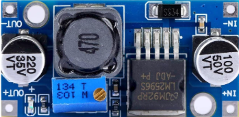
The BUCK DC/DC converter, manufactured by HUAREW, is a highly efficient DC-DC step-down voltage regulator. It is designed to convert a higher input voltage to a lower output voltage while increasing the output current. This component is widely used in power management systems due to its ability to minimize energy loss during the conversion process.
Explore Projects Built with BUCK


Explore Projects Built with BUCK
Common Applications and Use Cases
- Powering low-voltage devices from higher-voltage sources (e.g., 12V to 5V conversion)
- Battery-powered systems to regulate voltage levels
- Embedded systems and microcontrollers
- LED drivers and lighting systems
- Industrial and automotive power supplies
Technical Specifications
The following table outlines the key technical specifications of the HUAREW BUCK DC/DC converter:
| Parameter | Value |
|---|---|
| Input Voltage Range | 4.5V to 40V |
| Output Voltage Range | 1.25V to 37V |
| Maximum Output Current | 3A |
| Efficiency | Up to 92% |
| Switching Frequency | 150 kHz |
| Operating Temperature | -40°C to +85°C |
| Dimensions | 22mm x 17mm x 4mm |
Pin Configuration and Descriptions
The BUCK DC/DC converter typically has the following pin configuration:
| Pin Name | Description |
|---|---|
| VIN | Input voltage pin (connect to the power source) |
| VOUT | Output voltage pin (connect to the load) |
| GND | Ground pin (common ground for input and output) |
| ADJ | Adjustable pin (used to set the output voltage) |
Usage Instructions
How to Use the Component in a Circuit
Connect the Input Voltage (VIN):
Attach the input voltage source to the VIN pin. Ensure the input voltage is within the specified range (4.5V to 40V).Connect the Output Voltage (VOUT):
Connect the load to the VOUT pin. The output voltage can be adjusted using the ADJ pin.Set the Output Voltage:
Use a potentiometer or resistor divider connected to the ADJ pin to set the desired output voltage. Refer to the datasheet for the formula to calculate the resistor values.Ground Connections:
Connect the GND pin to the common ground of the circuit.Add Decoupling Capacitors:
Place appropriate input and output capacitors close to the VIN and VOUT pins to stabilize the voltage and reduce noise.
Important Considerations and Best Practices
- Heat Dissipation: Ensure proper heat dissipation, especially when operating at high currents. Use a heatsink or ensure adequate airflow if necessary.
- Input Voltage Range: Do not exceed the maximum input voltage of 40V to avoid damaging the component.
- Load Requirements: Ensure the load does not exceed the maximum output current of 3A.
- Switching Noise: If noise is a concern, use additional filtering components such as inductors or capacitors.
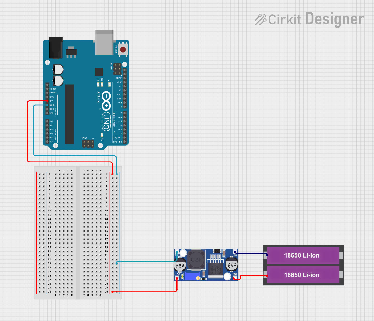
Example: Using the BUCK DC/DC with an Arduino UNO
The BUCK DC/DC converter can be used to power an Arduino UNO from a higher voltage source, such as a 12V battery. Below is an example circuit and code:
Circuit Connections
- Connect the 12V battery to the VIN pin of the BUCK converter.
- Adjust the output voltage to 5V using the ADJ pin.
- Connect the VOUT pin to the Arduino UNO's 5V pin.
- Connect the GND pin of the BUCK converter to the Arduino's GND.
Arduino Code Example
// Example code to blink an LED using an Arduino UNO powered by the BUCK DC/DC converter

const int ledPin = 13; // Pin connected to the onboard LED

void setup() {
  pinMode(ledPin, OUTPUT); // Set the LED pin as an output
}

void loop() {
  digitalWrite(ledPin, HIGH); // Turn the LED on
  delay(1000);               // Wait for 1 second
  digitalWrite(ledPin, LOW);  // Turn the LED off
  delay(1000);               // Wait for 1 second
}
Troubleshooting and FAQs
Common Issues and Solutions
No Output Voltage:
- Cause: Input voltage is not connected or is below the minimum required voltage.
- Solution: Verify the input voltage is within the 4.5V to 40V range.
Output Voltage is Incorrect:
- Cause: Incorrect adjustment of the ADJ pin or improper resistor values.
- Solution: Recalculate and adjust the resistor values or potentiometer to set the desired output voltage.
Overheating:
- Cause: Excessive current draw or insufficient heat dissipation.
- Solution: Reduce the load current or add a heatsink to the component.
High Noise or Ripple:
- Cause: Insufficient decoupling capacitors or poor layout.
- Solution: Add appropriate input and output capacitors close to the pins and ensure proper PCB layout.
FAQs
Q: Can the BUCK DC/DC converter be used with a 24V input to power a 5V device?
A: Yes, the converter can step down a 24V input to 5V, provided the output current does not exceed 3A.
Q: What is the efficiency of the BUCK DC/DC converter?
A: The efficiency can reach up to 92%, depending on the input voltage, output voltage, and load conditions.
Q: Can I use the BUCK DC/DC converter to power sensitive analog circuits?
A: Yes, but additional filtering components may be required to reduce switching noise.
Q: How do I calculate the resistor values for the ADJ pin?
A: Refer to the datasheet for the specific formula, which typically involves the desired output voltage and reference voltage.
This concludes the documentation for the HUAREW BUCK DC/DC converter.