
How to Use Screw terminal - 2 pins: Examples, Pinouts, and Specs

 Design with Screw terminal - 2 pins in Cirkit Designer
Introduction
The screw terminal (2 pins) is a type of electrical connector designed for securely attaching wires using screws. It features two pins, making it ideal for connecting two wires in a reliable and reusable manner. This component is widely used in applications where a robust and easily adjustable connection is required, such as in prototyping, industrial control systems, and power distribution.
Explore Projects Built with Screw terminal - 2 pins
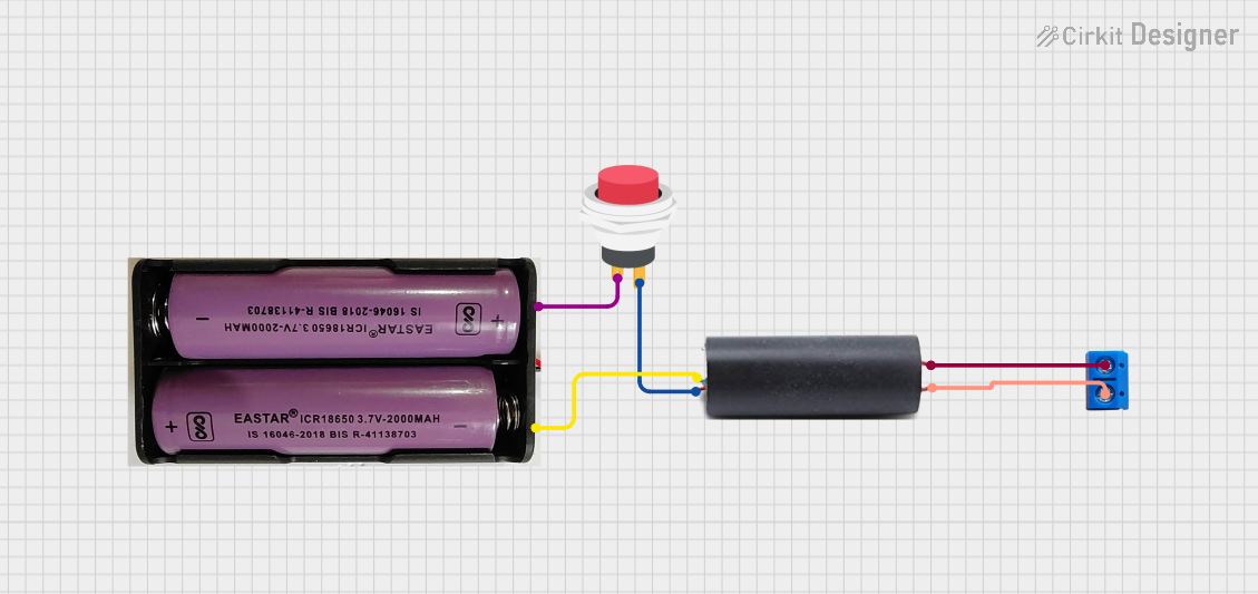 Open Project in Cirkit Designer
 Open Project in Cirkit Designer
 Open Project in Cirkit Designer
 Open Project in Cirkit Designer
Explore Projects Built with Screw terminal - 2 pins
Open Project in Cirkit DesignerOpen Project in Cirkit DesignerOpen Project in Cirkit DesignerOpen Project in Cirkit DesignerCommon Applications and Use Cases
- Connecting wires in prototyping and breadboard setups
- Industrial control systems and automation
- Power supply connections
- Audio and speaker wiring
- Home automation and IoT projects
Technical Specifications
The screw terminal (2 pins) is a simple yet versatile component. Below are its key technical details:
General Specifications
| Parameter | Value |
|---|---|
| Number of Pins | 2 |
| Wire Gauge Support | 16–26 AWG |
| Maximum Voltage Rating | 300V |
| Maximum Current Rating | 10A |
| Material | Plastic housing, metal screws |
| Mounting Type | PCB mount or free-standing |
| Screw Type | Slotted or Phillips head |
Pin Configuration and Descriptions
| Pin Number | Description |
|---|---|
| 1 | Connection point for wire 1 |
| 2 | Connection point for wire 2 |
Usage Instructions
How to Use the Screw Terminal in a Circuit
- Prepare the Wires: Strip approximately 5–7 mm of insulation from the ends of the wires you want to connect.
- Insert the Wires: Loosen the screws on the terminal using a screwdriver. Insert the stripped end of each wire into the corresponding pin slot.
- Secure the Wires: Tighten the screws to clamp the wires securely in place. Ensure the connection is firm but avoid overtightening, which could damage the wires or the terminal.
- Connect to Circuit: Solder the pins of the screw terminal to a PCB or connect them to other components as needed.
Important Considerations and Best Practices
- Wire Gauge Compatibility: Ensure the wires used are within the supported gauge range (16–26 AWG).
- Avoid Overloading: Do not exceed the maximum voltage (300V) or current (10A) ratings to prevent overheating or damage.
- Secure Connections: Double-check that the screws are tightened properly to avoid loose connections, which can lead to electrical faults.
- Use Insulated Tools: When working with live circuits, always use insulated tools to prevent accidental short circuits or electric shocks.
Example: Connecting to an Arduino UNO
While the screw terminal itself is not an active electronic component, it can be used to connect external devices (e.g., sensors, motors) to an Arduino UNO. Below is an example of how to use a screw terminal to connect a DC motor to an Arduino UNO via a motor driver.
// Example: Controlling a DC motor connected via a screw terminal
// Components: Arduino UNO, motor driver, DC motor, screw terminal

// Define motor control pins
const int motorPin1 = 9; // Motor driver input 1
const int motorPin2 = 10; // Motor driver input 2

void setup() {
  // Set motor pins as outputs
  pinMode(motorPin1, OUTPUT);
  pinMode(motorPin2, OUTPUT);
}

void loop() {
  // Rotate motor in one direction
  digitalWrite(motorPin1, HIGH); // Set pin 1 high
  digitalWrite(motorPin2, LOW);  // Set pin 2 low
  delay(2000); // Run for 2 seconds

  // Rotate motor in the opposite direction
  digitalWrite(motorPin1, LOW);  // Set pin 1 low
  digitalWrite(motorPin2, HIGH); // Set pin 2 high
  delay(2000); // Run for 2 seconds
}
Note: The screw terminal is used to connect the motor wires to the motor driver. Ensure the connections are secure and the motor driver is compatible with the motor's voltage and current requirements.
Troubleshooting and FAQs
Common Issues and Solutions
| Issue | Possible Cause | Solution |
|---|---|---|
| Loose wire connections | Screws not tightened properly | Tighten the screws securely. |
| Overheating of the terminal | Exceeding voltage or current ratings | Ensure the load is within the ratings. |
| Wire slipping out of the terminal | Insufficient wire stripping or clamping | Strip the wire properly and retighten. |
FAQs
Q: Can I use the screw terminal for high-frequency signals?
A: Screw terminals are generally not ideal for high-frequency signals due to potential impedance mismatches. For such applications, consider using specialized connectors.
Q: How do I prevent corrosion on the terminal?
A: Use terminals with corrosion-resistant materials or apply a thin layer of dielectric grease to the screws and wire ends.
Q: Can I reuse the screw terminal?
A: Yes, screw terminals are reusable. Simply loosen the screws, remove the wires, and reinsert new wires as needed.
Q: Is soldering required for the screw terminal?
A: Soldering is not required for the wire connections, but the terminal pins may need to be soldered to a PCB for a permanent setup.
By following these guidelines, you can effectively use the screw terminal (2 pins) in your projects for secure and reliable wire connections.