How to Use Adafruit Positive RGB 2x16 LCD: Examples, Pinouts, and Specs
Introduction
The Adafruit Positive RGB 2x16 LCD is a versatile and vibrant display module capable of showing up to 32 characters across two lines, with the added feature of a full RGB (Red, Green, Blue) backlight. This allows for a wide range of colors to be displayed behind the text, making it suitable for various applications such as user interfaces, status displays, simple games, and any project where visual feedback is necessary.
Explore Projects Built with Adafruit Positive RGB 2x16 LCD
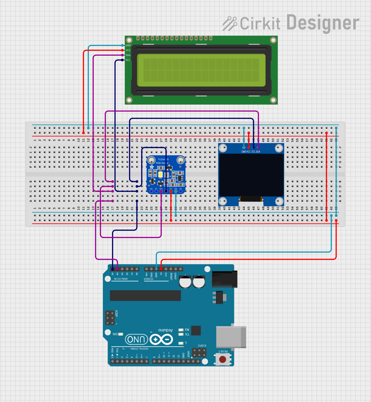
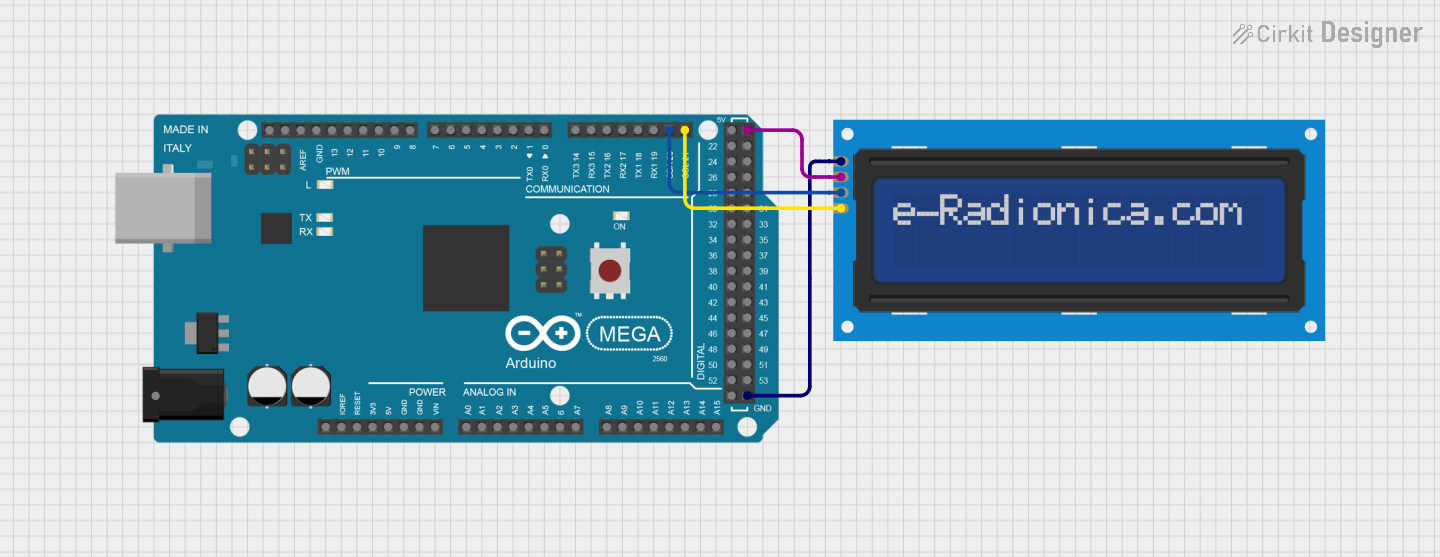
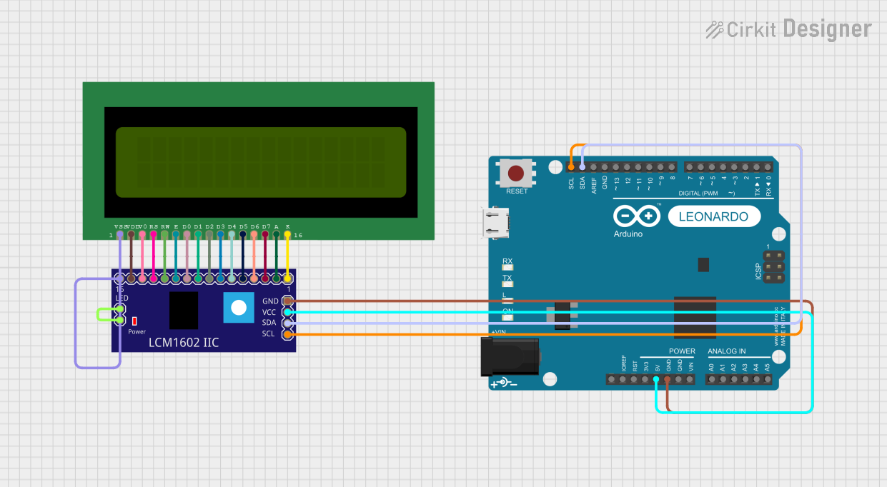
Explore Projects Built with Adafruit Positive RGB 2x16 LCD
Common Applications and Use Cases
- DIY electronics projects
- User interfaces for devices
- Status and information displays
- Clocks and timers
- Simple games and animations
Technical Specifications
Key Technical Details
- Display Type: Character LCD
- Display Format: 2 lines by 16 characters
- Backlight: RGB LED
- Communication: I2C interface
- Operating Voltage: 5V
- Logic Level: 3.3V/5V compatible
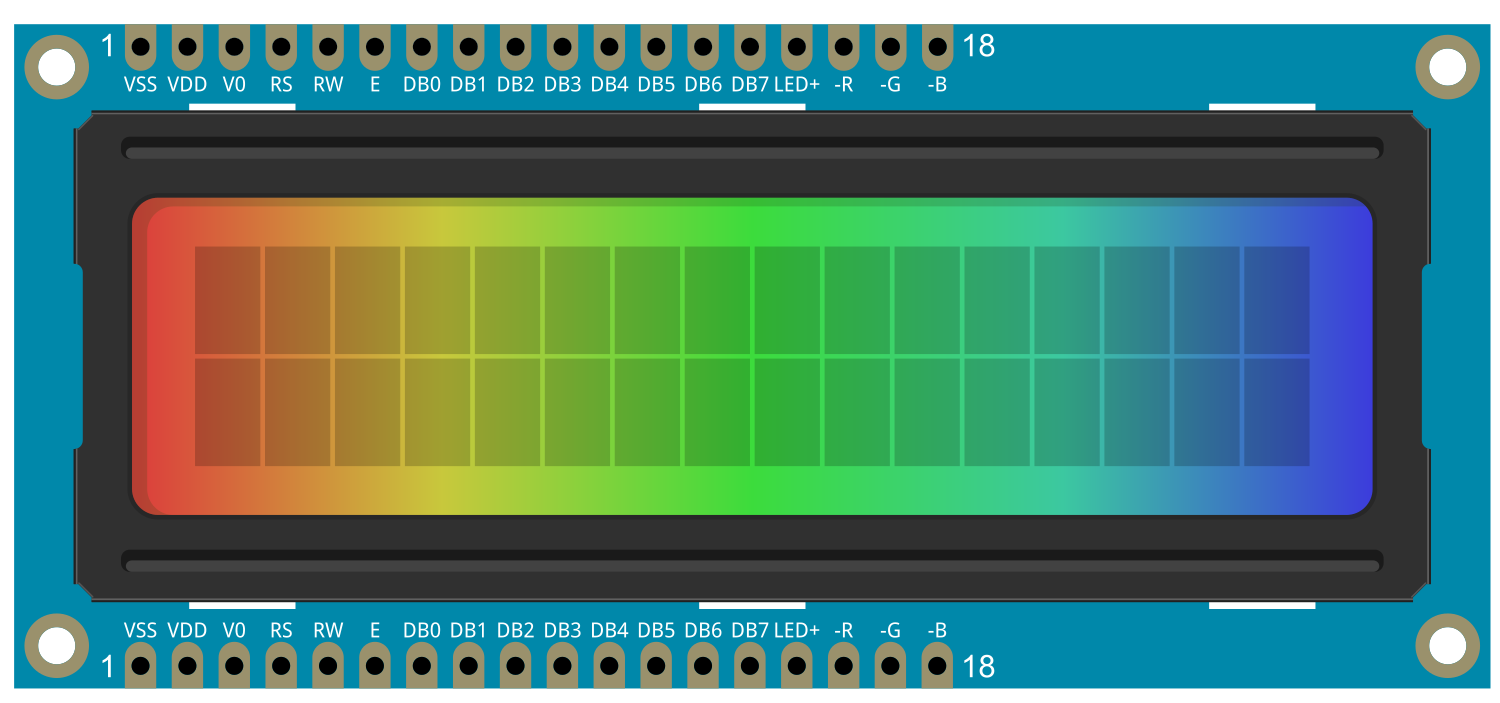
Pin Configuration and Descriptions
| Pin Number | Name | Description |
|---|---|---|
| 1 | GND | Ground connection |
| 2 | VCC | Power supply (5V) |
| 3 | SDA | I2C data line |
| 4 | SCL | I2C clock line |
| 5 | LED+ | Anode for the RGB backlight (5V) |
| 6 | R | Red cathode for the RGB backlight |
| 7 | G | Green cathode for the RGB backlight |
| 8 | B | Blue cathode for the RGB backlight |
Usage Instructions
How to Use the Component in a Circuit
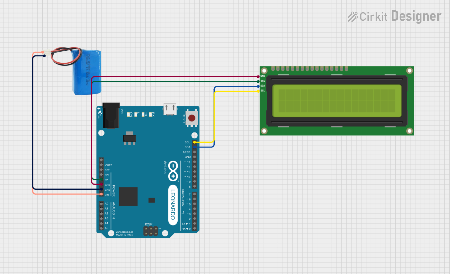
- Connect the GND pin to the ground of your power supply.
- Connect the VCC pin to a 5V supply.
- Connect the SDA and SCL pins to the I2C data and clock lines of your microcontroller, respectively.
- Optionally, connect the LED+ pin to 5V through a current-limiting resistor, and the R, G, and B pins to PWM-capable pins on your microcontroller to control the backlight color.
Important Considerations and Best Practices
- Always use a current-limiting resistor with the LED+ pin to prevent damage to the backlight.
- Ensure that the I2C lines have pull-up resistors, as they are required for proper communication.
- When using with a 3.3V logic level device, ensure that the I2C lines are level-shifted to be compatible with the 5V logic level of the LCD.
Example Code for Arduino UNO
#include <Wire.h>
#include <Adafruit_RGBLCDShield.h>

// Initialize the display with the I2C addr 0x7C
Adafruit_RGBLCDShield lcd = Adafruit_RGBLCDShield(0x7C >> 1);

void setup() {
  // Set up the LCD's number of columns and rows:
  lcd.begin(16, 2);

  // Set the backlight color to green
  lcd.setBacklight(0, 255, 0);
}

void loop() {
  // Print a message to the LCD.
  lcd.setCursor(0, 0);
  lcd.print("Hello, World!");
}
Troubleshooting and FAQs
Common Issues Users Might Face
- Display not powering on: Check the connections to VCC and GND, and ensure that the power supply is at 5V.
- Characters not displaying correctly: Verify that the I2C address used in the code matches the address of the LCD.
- Backlight not working: Ensure that the LED+ pin is connected to 5V with a current-limiting resistor and that the R, G, and B pins are correctly connected.
Solutions and Tips for Troubleshooting
- Double-check all wiring connections.
- Use a multimeter to verify that the correct voltages are present at the LCD pins.
- Make sure that the Arduino library for the Adafruit RGB LCD Shield is correctly installed.
- If using PWM to control the backlight, ensure that the correct pins are being used and that the Arduino code is correctly setting the PWM values.
FAQs
Q: Can I use this display with a 3.3V system? A: Yes, but you will need to ensure that the I2C lines are level-shifted to be compatible with the 5V logic level of the LCD.
Q: How do I change the backlight color? A: You can change the backlight color by adjusting the PWM values sent to the R, G, and B pins.
Q: What is the maximum current the backlight can draw? A: The maximum current for the backlight will depend on the current-limiting resistor used. Check the datasheet for the RGB LEDs used in the backlight for their maximum current ratings.