Cirkit Designer
Your all-in-one circuit design IDE
Home /
Component Documentation
How to Use a1: Examples, Pinouts, and Specs
Introduction
The A1 Amplifier Module is a versatile electronic component designed to increase the power of an input signal, making it suitable for a wide range of applications in audio, radio frequency (RF), and instrumentation systems. Its primary function is to amplify weak signals to levels that are more useful for further processing or output.
Explore Projects Built with a1
Arduino UNO and A9G GSM/GPRS GPS-Based Air Quality Monitoring System
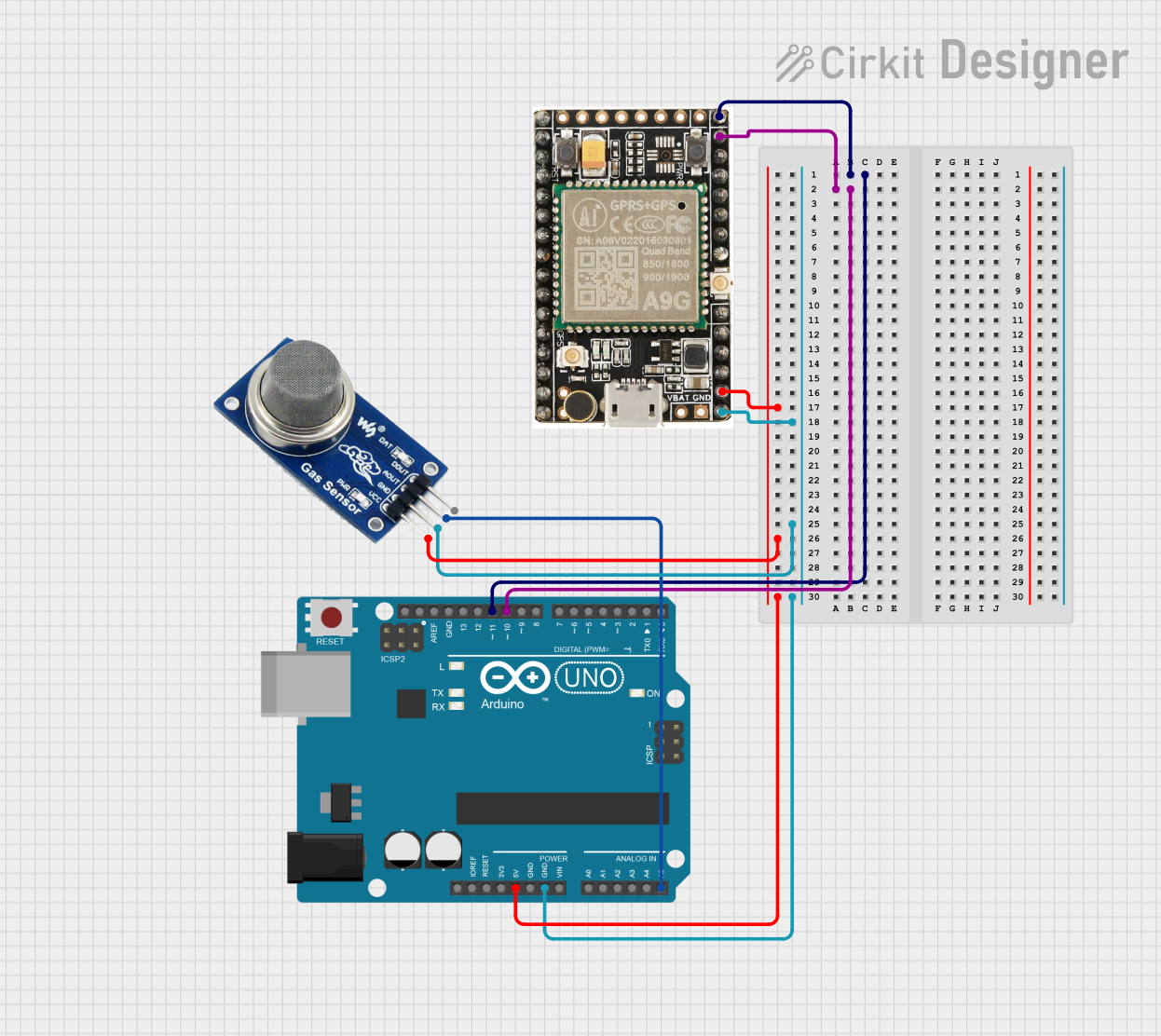
This circuit features an Arduino UNO microcontroller interfaced with an A9G GSM/GPRS+GPS module and an MQ2 gas sensor. The Arduino communicates with the A9G module via digital pins D11 and D10 for data transmission, and it reads analog gas concentration levels from the MQ2 sensor through analog pin A5. Both the A9G module and the MQ2 sensor are powered by the Arduino's 5V output, and all components share a common ground.
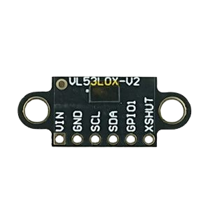
Arduino UNO with A9G GSM/GPRS and Dual VL53L1X Distance Sensors

This circuit features an Arduino UNO microcontroller interfaced with an A9G GSM/GPRS+GPS/BDS module and two VL53L1X time-of-flight distance sensors. The A9G module is connected to the Arduino via serial communication for GPS and GSM functionalities, while both VL53L1X sensors are connected through I2C with shared SDA and SCL lines and individual SHUT pins for selective sensor activation. The Arduino is programmed to control these peripherals, although the specific functionality is not detailed in the provided code.
Arduino UNO-Based Air Quality Monitoring System with OLED Display and Multi-Color LED Indicators
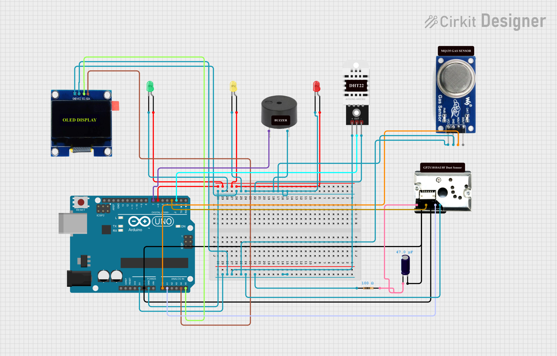
This circuit is an air quality monitoring system using an Arduino UNO, which integrates sensors for dust (GP2Y1010AU0F), gas (MQ135), and temperature/humidity (DHT22). The system displays real-time data on an OLED screen and uses LEDs and a buzzer to indicate air quality levels.
Solar-Powered GSM/GPRS+GPS Tracker with Seeeduino XIAO

This circuit features an Ai Thinker A9G development board for GSM/GPRS and GPS/BDS connectivity, interfaced with a Seeeduino XIAO microcontroller for control and data processing. A solar cell, coupled with a TP4056 charging module, charges a 3.3V battery, which powers the system through a 3.3V regulator ensuring stable operation. The circuit likely serves for remote data communication and location tracking, with the capability to be powered by renewable energy and interfaced with additional sensors or input devices via the Seeeduino XIAO.
Explore Projects Built with a1
Arduino UNO and A9G GSM/GPRS GPS-Based Air Quality Monitoring System
This circuit features an Arduino UNO microcontroller interfaced with an A9G GSM/GPRS+GPS module and an MQ2 gas sensor. The Arduino communicates with the A9G module via digital pins D11 and D10 for data transmission, and it reads analog gas concentration levels from the MQ2 sensor through analog pin A5. Both the A9G module and the MQ2 sensor are powered by the Arduino's 5V output, and all components share a common ground.
Arduino UNO with A9G GSM/GPRS and Dual VL53L1X Distance Sensors
This circuit features an Arduino UNO microcontroller interfaced with an A9G GSM/GPRS+GPS/BDS module and two VL53L1X time-of-flight distance sensors. The A9G module is connected to the Arduino via serial communication for GPS and GSM functionalities, while both VL53L1X sensors are connected through I2C with shared SDA and SCL lines and individual SHUT pins for selective sensor activation. The Arduino is programmed to control these peripherals, although the specific functionality is not detailed in the provided code.
Arduino UNO-Based Air Quality Monitoring System with OLED Display and Multi-Color LED Indicators
This circuit is an air quality monitoring system using an Arduino UNO, which integrates sensors for dust (GP2Y1010AU0F), gas (MQ135), and temperature/humidity (DHT22). The system displays real-time data on an OLED screen and uses LEDs and a buzzer to indicate air quality levels.
Solar-Powered GSM/GPRS+GPS Tracker with Seeeduino XIAO
This circuit features an Ai Thinker A9G development board for GSM/GPRS and GPS/BDS connectivity, interfaced with a Seeeduino XIAO microcontroller for control and data processing. A solar cell, coupled with a TP4056 charging module, charges a 3.3V battery, which powers the system through a 3.3V regulator ensuring stable operation. The circuit likely serves for remote data communication and location tracking, with the capability to be powered by renewable energy and interfaced with additional sensors or input devices via the Seeeduino XIAO.
Common Applications and Use Cases
- Audio amplification for speakers and headphones
- Signal boosting in communication systems
- Sensor signal conditioning
- Laboratory and educational projects
Technical Specifications
Key Technical Details
- Voltage Supply Range: 5V to 15V DC
- Input Signal Voltage Range: 10mV to 2V peak-to-peak
- Output Power: Depending on supply voltage and load impedance
- Frequency Response: 20Hz to 20kHz (audio range)
- Total Harmonic Distortion (THD): < 0.1% at rated power
- Gain: Adjustable with external components
Pin Configuration and Descriptions
| Pin Number | Name | Description |
|---|---|---|
| 1 | V+ | Positive supply voltage input |
| 2 | IN- | Inverting input |
| 3 | IN+ | Non-inverting input |
| 4 | OUT | Amplified output signal |
| 5 | GND | Ground reference |
Usage Instructions
How to Use the A1 Amplifier in a Circuit
- Power Supply: Connect the V+ pin to a DC power source within the specified voltage range and the GND pin to the system ground.
- Input Signal: Apply the input signal to the IN+ pin for non-inverting amplification or to the IN- pin for inverting amplification.
- Output: Connect the OUT pin to the load, ensuring it matches the amplifier's output power capabilities.
- Gain Setting: Use external resistors or potentiometers to set the desired gain level.
Important Considerations and Best Practices
- Ensure that the power supply voltage does not exceed the maximum rating to prevent damage.
- Use decoupling capacitors close to the power supply pins to minimize noise.
- Keep signal paths short and shielded where possible to reduce interference.
- Implement proper heat sinking if the module is expected to operate at high power levels.
Troubleshooting and FAQs
Common Issues
- Low Output Volume: Check the input signal level and gain settings. Ensure the power supply is adequate.
- Distortion: Verify that the input signal is within the acceptable range and that the power supply is stable.
- No Output: Ensure that all connections are secure and that the power supply is functioning.
Solutions and Tips for Troubleshooting
- Double-check wiring against the pin configuration table.
- Use an oscilloscope to verify the input and output signal integrity.
- Replace the module if it overheats or emits a burnt smell, indicating potential internal damage.
FAQs
Q: Can the A1 be used with an Arduino UNO?
- A: Yes, the A1 can be interfaced with an Arduino UNO for audio or signal processing projects.
Q: What is the maximum gain achievable with the A1?
- A: The maximum gain is determined by the external components used. Consult the datasheet for detailed calculations.
Example Code for Arduino UNO
// Example code to control the A1 Amplifier Module with an Arduino UNO

int inputPin = A0; // Analog input pin connected to the amplifier input
int outputPin = 9; // PWM output pin connected to the amplifier output

void setup() {
  pinMode(outputPin, OUTPUT);
  Serial.begin(9600);
}

void loop() {
  int sensorValue = analogRead(inputPin); // Read the input signal
  int outputValue = map(sensorValue, 0, 1023, 0, 255); // Map to PWM range
  analogWrite(outputPin, outputValue); // Send PWM signal to amplifier

  // For debugging purposes, print the values to the Serial Monitor
  Serial.print("Input Signal: ");
  Serial.print(sensorValue);
  Serial.print("\t Output PWM: ");
  Serial.println(outputValue);

  delay(10); // Short delay for stability
}
Note: The above code is a simple demonstration of how to interface the A1 Amplifier Module with an Arduino UNO. It reads an analog input, maps the value to a PWM signal, and outputs it to the amplifier. Adjust the code to suit the specific requirements of your application.