How to Use ESP32-Cam Terminal Breakout Board: Examples, Pinouts, and Specs
Introduction
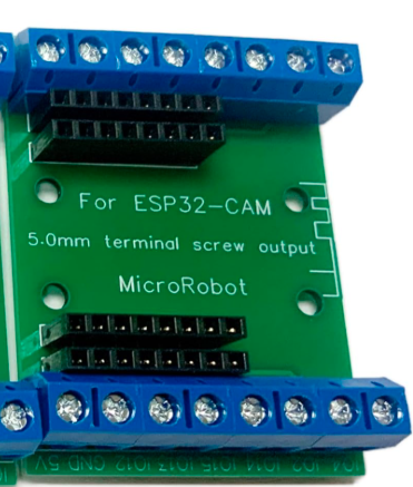
The ESP32-Cam Terminal Breakout Board by MicroRobot (Part ID: ESP32-Cam Breakout Board) is a versatile accessory designed to simplify the use of the ESP32-Cam module. This breakout board provides easy access to the ESP32-Cam's GPIO pins, power connections, and programming interfaces, making it an essential tool for prototyping and developing IoT applications with camera capabilities.
Explore Projects Built with ESP32-Cam Terminal Breakout Board


Explore Projects Built with ESP32-Cam Terminal Breakout Board
Common Applications and Use Cases
- IoT projects requiring video streaming or image capture
- Smart home devices with camera functionality
- Remote monitoring and surveillance systems
- AI and machine learning applications (e.g., facial recognition)
- Prototyping and testing ESP32-Cam-based designs
Technical Specifications
The ESP32-Cam Terminal Breakout Board is designed to complement the ESP32-Cam module by providing a user-friendly interface for connections and programming. Below are the key technical details:
Key Features
- Input Voltage: 5V (via micro-USB or external power supply)
- GPIO Access: Terminal blocks for all ESP32-Cam GPIO pins
- Programming Interface: Integrated FTDI header for UART communication
- Dimensions: 50mm x 40mm x 10mm
- Operating Temperature: -40°C to 85°C
- Compatibility: Designed specifically for the ESP32-Cam module
Pin Configuration and Descriptions
The breakout board provides terminal blocks and headers for easy access to the ESP32-Cam's pins. Below is the pinout description:
| Pin Name | Description |
|---|---|
| 3V3 | 3.3V power output (regulated from the ESP32-Cam module) |
| GND | Ground connection |
| GPIO0 | General-purpose I/O pin; used for boot mode selection during programming |
| GPIO1 | General-purpose I/O pin |
| GPIO2 | General-purpose I/O pin |
| GPIO3 | General-purpose I/O pin |
| GPIO4 | General-purpose I/O pin |
| GPIO12 | General-purpose I/O pin |
| GPIO13 | General-purpose I/O pin |
| GPIO14 | General-purpose I/O pin |
| GPIO15 | General-purpose I/O pin |
| GPIO16 | General-purpose I/O pin |
| GPIO17 | General-purpose I/O pin |
| TXD | UART Transmit pin (used for programming and debugging) |
| RXD | UART Receive pin (used for programming and debugging) |
| 5V | 5V power input (used to power the ESP32-Cam module) |
| RST | Reset pin for the ESP32-Cam module |
Usage Instructions
How to Use the Component in a Circuit
Powering the Board:
- Connect a 5V power supply to the
5VandGNDterminals or use the micro-USB port. - Ensure the power supply can provide at least 500mA to avoid instability.
- Connect a 5V power supply to the
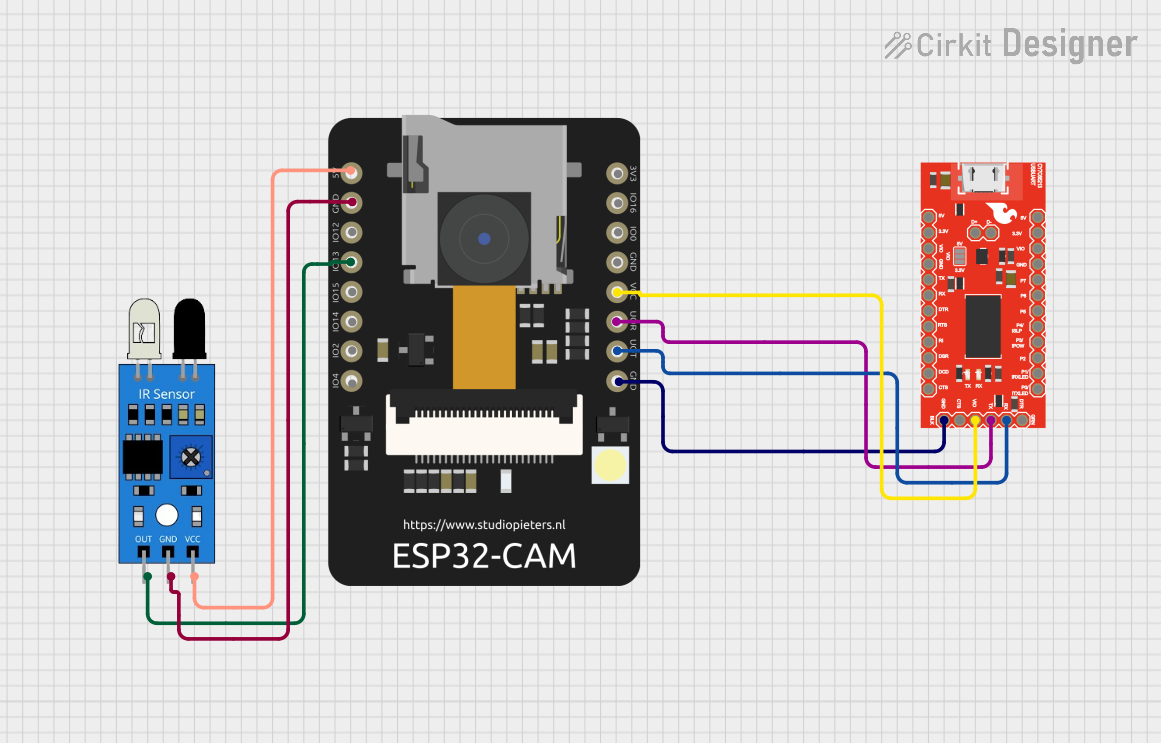
Connecting the ESP32-Cam:
- Insert the ESP32-Cam module into the breakout board's socket, ensuring proper alignment.
- Use the terminal blocks to connect external components (e.g., sensors, LEDs) to the GPIO pins.
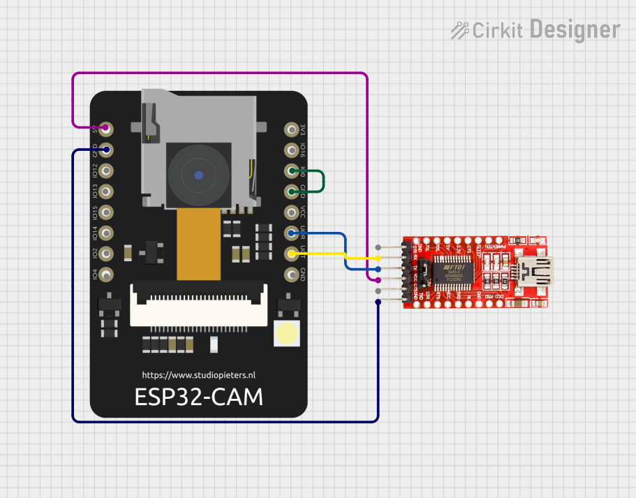
Programming the ESP32-Cam:
- Connect an FTDI programmer to the UART header (TXD, RXD, GND, and 5V).
- Set GPIO0 to LOW (connect to GND) to enable programming mode.
- Use the Arduino IDE or other compatible software to upload code.
Using the GPIO Pins:
- Use the terminal blocks to connect peripherals like relays, motors, or sensors.
- Refer to the ESP32-Cam datasheet for GPIO pin capabilities (e.g., PWM, ADC, I2C).
Important Considerations and Best Practices
- Power Supply: Ensure a stable 5V power source to avoid brownouts during operation.
- GPIO Voltage Levels: The ESP32-Cam operates at 3.3V logic levels. Use level shifters if interfacing with 5V devices.
- Programming Mode: Always set GPIO0 to LOW before uploading code, and reset the board after programming.
- Heat Management: The ESP32-Cam can get warm during operation. Ensure adequate ventilation.
Example Code for Arduino UNO Integration
Below is an example of how to use the ESP32-Cam with the Arduino IDE to capture an image and display it on a web server:
#include <WiFi.h>
#include <esp_camera.h>

// Replace with your network credentials
const char* ssid = "Your_SSID";
const char* password = "Your_PASSWORD";

// Camera configuration
#define PWDN_GPIO_NUM    -1
#define RESET_GPIO_NUM   -1
#define XCLK_GPIO_NUM     0
#define SIOD_GPIO_NUM    26
#define SIOC_GPIO_NUM    27
#define Y9_GPIO_NUM      35
#define Y8_GPIO_NUM      34
#define Y7_GPIO_NUM      39
#define Y6_GPIO_NUM      36
#define Y5_GPIO_NUM      21
#define Y4_GPIO_NUM      19
#define Y3_GPIO_NUM      18
#define Y2_GPIO_NUM       5
#define VSYNC_GPIO_NUM   25
#define HREF_GPIO_NUM    23
#define PCLK_GPIO_NUM    22

void startCameraServer();

void setup() {
  Serial.begin(115200);

  // Connect to Wi-Fi
  WiFi.begin(ssid, password);
  while (WiFi.status() != WL_CONNECTED) {
    delay(500);
    Serial.print(".");
  }
  Serial.println("\nWiFi connected");

  // Initialize the camera
  camera_config_t config;
  config.ledc_channel = LEDC_CHANNEL_0;
  config.ledc_timer = LEDC_TIMER_0;
  config.pin_d0 = Y2_GPIO_NUM;
  config.pin_d1 = Y3_GPIO_NUM;
  config.pin_d2 = Y4_GPIO_NUM;
  config.pin_d3 = Y5_GPIO_NUM;
  config.pin_d4 = Y6_GPIO_NUM;
  config.pin_d5 = Y7_GPIO_NUM;
  config.pin_d6 = Y8_GPIO_NUM;
  config.pin_d7 = Y9_GPIO_NUM;
  config.pin_xclk = XCLK_GPIO_NUM;
  config.pin_pclk = PCLK_GPIO_NUM;
  config.pin_vsync = VSYNC_GPIO_NUM;
  config.pin_href = HREF_GPIO_NUM;
  config.pin_sscb_sda = SIOD_GPIO_NUM;
  config.pin_sscb_scl = SIOC_GPIO_NUM;
  config.pin_pwdn = PWDN_GPIO_NUM;
  config.pin_reset = RESET_GPIO_NUM;
  config.xclk_freq_hz = 20000000;
  config.pixel_format = PIXFORMAT_JPEG;

  if (psramFound()) {
    config.frame_size = FRAMESIZE_UXGA;
    config.jpeg_quality = 10;
    config.fb_count = 2;
  } else {
    config.frame_size = FRAMESIZE_SVGA;
    config.jpeg_quality = 12;
    config.fb_count = 1;
  }

  // Initialize the camera
  esp_err_t err = esp_camera_init(&config);
  if (err != ESP_OK) {
    Serial.printf("Camera init failed with error 0x%x", err);
    return;
  }

  // Start the camera server
  startCameraServer();
  Serial.println("Camera ready! Use 'http://<ESP32-Cam-IP>' to view the stream.");
}

void loop() {
  // Nothing to do here
}
Troubleshooting and FAQs
Common Issues and Solutions
ESP32-Cam Not Detected During Programming:
- Ensure GPIO0 is connected to GND before uploading code.
- Verify the FTDI programmer is connected correctly (TXD to RXD, RXD to TXD).
- Check that the FTDI programmer is set to 3.3V mode.
Brownout Resets:
- Use a stable 5V power supply capable of providing at least 500mA.
- Avoid powering the ESP32-Cam through the FTDI programmer.
No Video Stream:
- Verify the Wi-Fi credentials in the code.
- Check the serial monitor for error messages during initialization.
Overheating:
- Ensure proper ventilation around the ESP32-Cam module.
- Reduce the frame size or disable the camera when not in use.
FAQs
Can I use this breakout board with other ESP32 modules? No, this breakout board is specifically designed for the ESP32-Cam module.
What is the maximum current draw of the ESP32-Cam? The ESP32-Cam can draw up to 300mA during operation, so ensure your power supply can handle this.
Do I need additional components to use this breakout board? No, the breakout board provides all necessary connections for the ESP32-Cam. However, you may need an FTDI programmer for uploading code.