How to Use 3 way switch: Examples, Pinouts, and Specs

Introduction
A 3 way switch, manufactured by Import\Japan, is a type of electrical switch designed to control a single light or fixture from two different locations. This functionality makes it ideal for applications where lighting needs to be accessed from multiple points, such as in hallways, staircases, or large rooms. The switch operates by redirecting the electrical current between two traveler wires, enabling seamless control of the connected light or fixture.
Explore Projects Built with 3 way switch

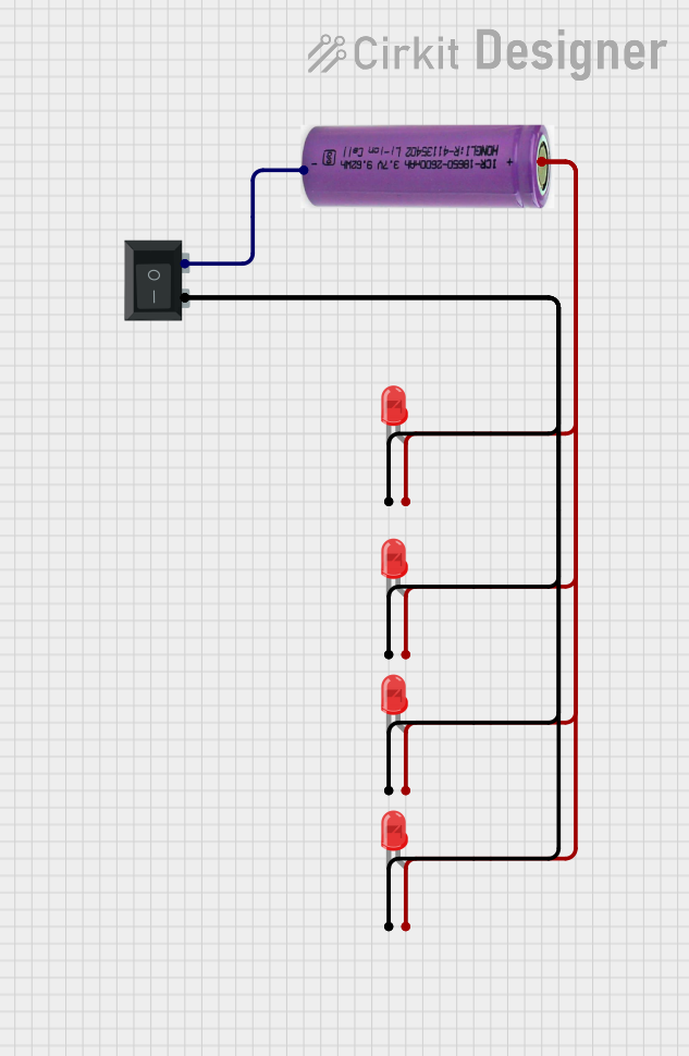
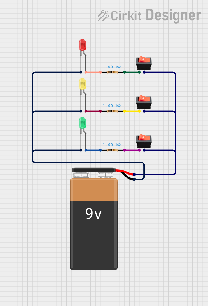
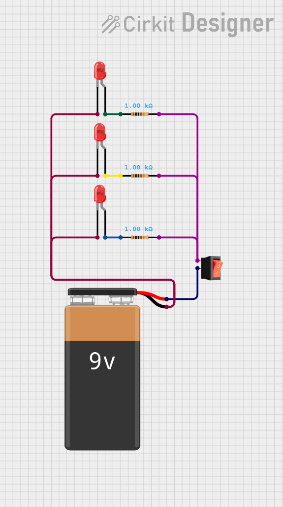
Explore Projects Built with 3 way switch
Common Applications and Use Cases
- Hallways and staircases for convenient lighting control from both ends.
- Large rooms with multiple entry points.
- Outdoor lighting systems with dual access points.
- Commercial spaces requiring flexible lighting control.
Technical Specifications
Key Technical Details
- Manufacturer: Import\Japan
- Switch Type: Mechanical toggle or rocker switch
- Voltage Rating: 120V AC or 240V AC (depending on model)
- Current Rating: 15A or 20A (depending on model)
- Number of Terminals: 3 (Common, Traveler 1, Traveler 2)
- Material: Flame-retardant plastic housing with copper or brass terminals
- Mounting Style: Standard wall box installation
- Operating Temperature: -20°C to 60°C
Pin Configuration and Descriptions
The 3 way switch has three terminals, as described in the table below:
| Terminal Name | Description |
|---|---|
| Common (COM) | Connects to the power source or the load (light/fixture). |
| Traveler 1 (T1) | Connects to one of the traveler wires leading to the second 3 way switch. |
| Traveler 2 (T2) | Connects to the other traveler wire leading to the second 3 way switch. |
Usage Instructions
How to Use the Component in a Circuit
- Understand the Wiring: A 3 way switch requires two switches and a light fixture. The switches are connected via two traveler wires, and the light is connected to the common terminal of one switch.
- Wiring Steps:
- Turn off the power supply to the circuit.
- Connect the power source (live wire) to the common terminal (COM) of the first switch.
- Connect the two traveler wires between the traveler terminals (T1 and T2) of both switches.
- Connect the common terminal (COM) of the second switch to the light fixture.
- Connect the neutral wire from the power source directly to the light fixture.
- Ensure all connections are secure and insulated.
- Test the Circuit: Turn the power back on and test the switches to ensure the light can be controlled from both locations.
Important Considerations and Best Practices
- Always turn off the power supply before working on the circuit to avoid electrical shock.
- Use appropriate wire gauges (e.g., 14 AWG for 15A circuits or 12 AWG for 20A circuits).
- Ensure the switch is rated for the voltage and current of your circuit.
- Use a multimeter to verify connections and continuity before powering the circuit.
- Follow local electrical codes and regulations for safe installation.
Arduino Integration
While a 3 way switch is typically used in AC circuits, it can also be simulated in low-voltage DC circuits for educational purposes. Below is an example of how to simulate a 3 way switch using an Arduino UNO and two push buttons:
// Simulating a 3 way switch using Arduino UNO
// Two push buttons control an LED, mimicking a 3 way switch setup.

const int button1Pin = 2; // Pin for first push button
const int button2Pin = 3; // Pin for second push button
const int ledPin = 13;    // Pin for LED

bool ledState = false;    // Tracks the state of the LED

void setup() {
  pinMode(button1Pin, INPUT_PULLUP); // Set button1 pin as input with pull-up resistor
  pinMode(button2Pin, INPUT_PULLUP); // Set button2 pin as input with pull-up resistor
  pinMode(ledPin, OUTPUT);           // Set LED pin as output
}

void loop() {
  // Check if button1 is pressed
  if (digitalRead(button1Pin) == LOW) {
    delay(50); // Debounce delay
    if (digitalRead(button1Pin) == LOW) {
      ledState = !ledState; // Toggle LED state
      digitalWrite(ledPin, ledState);
      while (digitalRead(button1Pin) == LOW); // Wait for button release
    }
  }

  // Check if button2 is pressed
  if (digitalRead(button2Pin) == LOW) {
    delay(50); // Debounce delay
    if (digitalRead(button2Pin) == LOW) {
      ledState = !ledState; // Toggle LED state
      digitalWrite(ledPin, ledState);
      while (digitalRead(button2Pin) == LOW); // Wait for button release
    }
  }
}
Troubleshooting and FAQs
Common Issues Users Might Face
Light Does Not Turn On:
- Ensure the power supply is connected and turned on.
- Verify all wiring connections are secure and correct.
- Check the light bulb for damage or failure.
Switches Do Not Work as Expected:
- Confirm that the traveler wires are correctly connected between the two switches.
- Ensure the common terminal is connected to the correct wire (power source or light).
Flickering Light:
- Check for loose connections or damaged wires.
- Ensure the switch is rated for the load being controlled.
Overheating Switch:
- Verify the switch is not overloaded (exceeding its current rating).
- Inspect for any short circuits or improper wiring.
Solutions and Tips for Troubleshooting
- Use a multimeter to test continuity and voltage at each terminal.
- Double-check the wiring diagram to ensure proper connections.
- Replace the switch if it is physically damaged or malfunctioning.
- Consult a licensed electrician if you are unsure about the installation or troubleshooting process.