How to Use ESP32S3-board: Examples, Pinouts, and Specs
Introduction
The ESP32S3 board, manufactured by Custom, is a versatile and powerful microcontroller designed for Internet of Things (IoT) applications. It features dual-core processing, integrated Wi-Fi and Bluetooth connectivity, and a wide array of GPIO pins. This board is ideal for projects requiring wireless communication, edge computing, or advanced sensor integration. Its robust performance and support for various peripherals make it a popular choice for hobbyists, developers, and engineers alike.
Explore Projects Built with ESP32S3-board


Explore Projects Built with ESP32S3-board
Common Applications and Use Cases
- Smart home devices (e.g., smart lights, thermostats)
- Wearable technology
- Industrial IoT systems
- Wireless sensor networks
- Robotics and automation
- Edge AI and machine learning applications
Technical Specifications
The ESP32S3 board offers a rich set of features and capabilities. Below are its key technical specifications:
| Specification | Details |
|---|---|
| Processor | Dual-core Xtensa® LX7, up to 240 MHz |
| Wireless Connectivity | Wi-Fi 802.11 b/g/n (2.4 GHz), Bluetooth 5.0 LE |
| Flash Memory | 4 MB (expandable, depending on the variant) |
| SRAM | 512 KB internal, with additional PSRAM support |
| GPIO Pins | 45 (configurable for digital I/O, ADC, DAC, PWM, etc.) |
| ADC Channels | 14 channels, 12-bit resolution |
| DAC Channels | 2 channels, 8-bit resolution |
| Communication Interfaces | UART, SPI, I2C, I2S, CAN, RMT, and USB OTG |
| Operating Voltage | 3.3V |
| Power Supply | USB-C (5V input) or external 3.3V source |
| Dimensions | 50 mm x 25 mm |
| Operating Temperature | -40°C to +85°C |
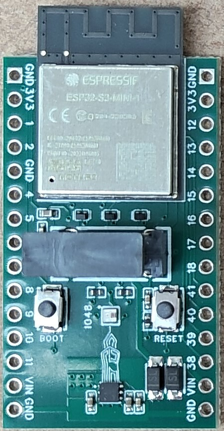
Pin Configuration and Descriptions
The ESP32S3 board has a flexible pinout. Below is a table summarizing the key pins and their functions:
| Pin | Name | Description |
|---|---|---|
| 1 | GND | Ground pin |
| 2 | 3V3 | 3.3V power output |
| 3 | EN | Enable pin (active high) |
| 4 | GPIO0 | General-purpose I/O, used for boot mode selection |
| 5 | GPIO1-45 | Configurable GPIO pins for digital I/O, ADC, DAC, PWM, etc. |
| 6 | TXD0/RXD0 | UART0 transmit/receive pins (default serial communication) |
| 7 | SCL/SDA | I2C clock and data lines |
| 8 | MOSI/MISO/SCK | SPI interface pins |
| 9 | USB_DM/USB_DP | USB data lines for OTG functionality |
| 10 | VBUS | USB power input (5V) |
Usage Instructions
How to Use the ESP32S3 Board in a Circuit
Powering the Board:
- Connect the board to a USB-C cable for power and programming.
- Alternatively, supply 3.3V to the 3V3 pin and connect GND to the ground of your circuit.
Programming the Board:
- Install the Arduino IDE or ESP-IDF for development.
- Add the ESP32 board package to the Arduino IDE via the Board Manager.
- Select "ESP32S3" as the target board and the correct COM port.
Connecting Peripherals:
- Use the GPIO pins for connecting sensors, actuators, or other peripherals.
- Ensure the voltage levels of connected devices are compatible with the 3.3V logic of the ESP32S3.
Uploading Code:
- Write your code in the Arduino IDE or ESP-IDF.
- Press the "Upload" button in the IDE to flash the code to the board.
- If required, hold the BOOT button during the upload process.
Important Considerations and Best Practices
- Voltage Levels: Ensure all connected devices operate at 3.3V logic levels to avoid damaging the board.
- Power Supply: Use a stable power source to prevent unexpected resets or malfunctions.
- GPIO Usage: Avoid using reserved pins (e.g., GPIO0, GPIO2) for general I/O, as they may interfere with boot modes.
- Heat Management: If running intensive tasks, consider adding a heatsink to manage heat dissipation.
Example Code for Arduino UNO Integration
Below is an example of using the ESP32S3 to read a temperature sensor and send data via Wi-Fi:
#include <WiFi.h> // Include the Wi-Fi library

// Wi-Fi credentials
const char* ssid = "Your_SSID";
const char* password = "Your_PASSWORD";

// Pin configuration
const int tempSensorPin = 34; // GPIO34 for analog input

void setup() {
  Serial.begin(115200); // Initialize serial communication
  pinMode(tempSensorPin, INPUT); // Set the sensor pin as input

  // Connect to Wi-Fi
  Serial.print("Connecting to Wi-Fi");
  WiFi.begin(ssid, password);
  while (WiFi.status() != WL_CONNECTED) {
    delay(500);
    Serial.print(".");
  }
  Serial.println("\nWi-Fi connected!");
}

void loop() {
  // Read temperature sensor value
  int sensorValue = analogRead(tempSensorPin);
  float voltage = sensorValue * (3.3 / 4095.0); // Convert ADC value to voltage
  float temperature = (voltage - 0.5) * 100.0; // Convert voltage to temperature

  // Print temperature to Serial Monitor
  Serial.print("Temperature: ");
  Serial.print(temperature);
  Serial.println(" °C");

  delay(2000); // Wait 2 seconds before the next reading
}
Troubleshooting and FAQs
Common Issues and Solutions
Board Not Detected by Computer:
- Ensure the USB-C cable supports data transfer (not just charging).
- Check if the correct COM port is selected in the IDE.
Code Upload Fails:
- Hold the BOOT button while uploading the code.
- Verify that the correct board and port are selected in the IDE.
Wi-Fi Connection Issues:
- Double-check the SSID and password in your code.
- Ensure the Wi-Fi network operates on the 2.4 GHz band (not 5 GHz).
Unstable Operation:
- Use a stable power source with sufficient current (at least 500 mA).
- Avoid connecting high-power peripherals directly to the GPIO pins.
FAQs
Q: Can the ESP32S3 board run on battery power?
A: Yes, the board can be powered by a 3.7V LiPo battery with a suitable voltage regulator.
Q: Does the ESP32S3 support over-the-air (OTA) updates?
A: Yes, the ESP32S3 supports OTA updates, allowing you to upload new firmware wirelessly.
Q: Can I use the ESP32S3 for machine learning applications?
A: Absolutely! The ESP32S3 has hardware acceleration for AI tasks and supports frameworks like TensorFlow Lite.
Q: Is the ESP32S3 compatible with Arduino libraries?
A: Yes, the ESP32S3 is fully compatible with most Arduino libraries, making it easy to integrate into existing projects.