How to Use type a to type c: Examples, Pinouts, and Specs
Introduction
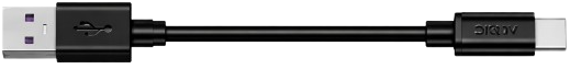
The Arduino Type A to Type C adapter is a compact and reliable component designed to bridge the gap between USB Type-A and USB Type-C interfaces. This adapter allows seamless connectivity between devices with older USB Type-A ports and modern devices equipped with USB Type-C ports. It is ideal for data transfer, charging, and interfacing with USB peripherals.
Explore Projects Built with type a to type c


Explore Projects Built with type a to type c
Common Applications and Use Cases
- Connecting USB Type-C devices (e.g., smartphones, tablets) to Type-A ports on computers or chargers.
- Enabling compatibility between legacy USB devices and modern Type-C interfaces.
- Power delivery and charging for Type-C devices.
- Data transfer between Type-A and Type-C devices.
Technical Specifications
The Arduino Type A to Type C adapter is designed to meet the latest USB standards, ensuring reliable performance and compatibility.
Key Technical Details
| Parameter | Specification |
|---|---|
| Manufacturer | Arduino |
| Part ID | Type A to Type C |
| USB Standard | USB 2.0 / USB 3.0 (backward compatible) |
| Maximum Current Support | 3A (for charging applications) |
| Data Transfer Rate | Up to 5 Gbps (USB 3.0) |
| Connector 1 (Input) | USB Type-A Male |
| Connector 2 (Output) | USB Type-C Female |
| Dimensions | 30mm x 12mm x 6mm |
| Material | Durable ABS plastic housing |
| Operating Temperature | -10°C to 50°C |
Pin Configuration and Descriptions
The adapter does not have discrete pins for user access but instead maps the USB Type-A and Type-C connections internally. Below is a simplified mapping of the key signals:
| USB Type-A Pin | USB Type-C Pin | Description |
|---|---|---|
| VBUS (Pin 1) | VBUS (Pin A4) | Power supply (5V) |
| D- (Pin 2) | D- (Pin A6) | Data transfer (negative) |
| D+ (Pin 3) | D+ (Pin A7) | Data transfer (positive) |
| GND (Pin 4) | GND (Pin B4) | Ground |
Usage Instructions
How to Use the Adapter in a Circuit
- Connecting Devices: Plug the USB Type-A male connector into a USB Type-A port on your computer, charger, or other host device.
- Connecting Peripherals: Attach the USB Type-C cable or device to the female Type-C port on the adapter.
- Power Delivery: Ensure the host device supports the required current for charging applications (up to 3A).
- Data Transfer: For high-speed data transfer, use a USB 3.0-compatible Type-A port and cable.
Important Considerations and Best Practices
- Compatibility: Verify that the host device supports the USB standard required by the connected Type-C device.
- Power Limitations: Do not exceed the maximum current rating of 3A to avoid overheating or damage.
- Cable Quality: Use high-quality USB cables to ensure reliable data transfer and charging performance.
- Orientation: The USB Type-C connector is reversible, so it can be inserted in either orientation.
Example: Using the Adapter with an Arduino UNO
The Type A to Type C adapter can be used to connect an Arduino UNO to a modern computer with only USB Type-C ports. Below is an example of how to upload a simple sketch to the Arduino UNO using this adapter.
Arduino Code Example
// Blink example for Arduino UNO
// This code blinks the onboard LED connected to pin 13
// Ensure the Type A to Type C adapter is properly connected
// between the Arduino UNO and your computer.

void setup() {
  pinMode(13, OUTPUT); // Set pin 13 as an output
}

void loop() {
  digitalWrite(13, HIGH); // Turn the LED on
  delay(1000);            // Wait for 1 second
  digitalWrite(13, LOW);  // Turn the LED off
  delay(1000);            // Wait for 1 second
}
Troubleshooting and FAQs
Common Issues Users Might Face
Device Not Recognized:
- Ensure the adapter is securely connected to both the Type-A port and the Type-C device.
- Verify that the host device supports the USB standard required by the connected device.
Slow Charging:
- Check if the host device provides sufficient current for charging.
- Use a high-quality USB cable to minimize resistance and power loss.
Data Transfer Fails:
- Confirm that the USB Type-A port supports data transfer (some ports are power-only).
- Ensure the connected Type-C device is in data transfer mode (if applicable).
Solutions and Tips for Troubleshooting
- Inspect Connections: Check for loose or damaged connectors on the adapter or cables.
- Test with Another Device: Try connecting a different Type-C device to isolate the issue.
- Update Drivers: Ensure the host device has the latest USB drivers installed.
- Replace Cables: If issues persist, test with a different USB cable to rule out cable faults.
By following this documentation, users can effectively utilize the Arduino Type A to Type C adapter for a wide range of applications, ensuring reliable performance and compatibility.