How to Use TMC2209: Examples, Pinouts, and Specs
Introduction
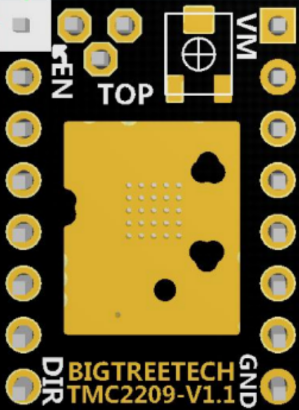
The TMC2209, manufactured by BIGTREETECH (Part ID: 2209), is a highly efficient and versatile stepper motor driver designed for applications requiring precise motor control. It is widely used in 3D printers, CNC machines, and other motion control systems. The TMC2209 is known for its silent operation, thanks to StealthChop2 technology, and advanced features such as stall detection, microstepping control, and current regulation.
Explore Projects Built with TMC2209

Explore Projects Built with TMC2209
Common Applications and Use Cases
- 3D printers for smooth and quiet motor operation
- CNC machines for precise motion control
- Robotics and automation systems
- Any application requiring low-noise stepper motor control
Technical Specifications
The TMC2209 offers a range of features and specifications that make it suitable for demanding applications. Below are the key technical details:
Key Technical Details
- Operating Voltage (V_M): 4.75V to 29V
- Logic Voltage (V_IO): 3.3V or 5V
- Maximum Motor Current (I_RMS): 2.0A (peak up to 2.8A)
- Microstepping: Up to 256 microsteps per full step
- Control Interface: UART or Step/Dir
- Features: StealthChop2, SpreadCycle, StallGuard4, CoolStep
- Package Type: QFN28 (4x4mm)
Pin Configuration and Descriptions
The TMC2209 comes in a 28-pin QFN package. Below is the pin configuration and description:
| Pin Number | Pin Name | Description |
|---|---|---|
| 1 | GND | Ground connection |
| 2 | V_M | Motor power supply (4.75V to 29V) |
| 3 | V_IO | Logic voltage supply (3.3V or 5V) |
| 4 | EN | Enable input (active low) |
| 5 | DIR | Direction input for Step/Dir interface |
| 6 | STEP | Step input for Step/Dir interface |
| 7 | UART | UART data input/output for configuration and control |
| 8 | MS1 | Microstep resolution selection (with MS2) |
| 9 | MS2 | Microstep resolution selection (with MS1) |
| 10 | DIAG | Diagnostic output (e.g., stall detection) |
| 11 | INDEX | Index output (indicates full step position) |
| 12 | VREF | Reference voltage for current setting |
| 13-20 | OUT1A, OUT1B, OUT2A, OUT2B | Motor coil outputs (connect to stepper motor windings) |
| 21 | CFG1 | Configuration pin 1 (e.g., UART mode selection) |
| 22 | CFG2 | Configuration pin 2 (e.g., UART mode selection) |
| 23 | CLK | External clock input (optional) |
| 24 | NC | No connection |
| 25-28 | GND | Ground connections |
Usage Instructions
The TMC2209 can be used in a variety of configurations, depending on the application. Below are the steps and considerations for using the TMC2209 in a circuit.
How to Use the TMC2209 in a Circuit
Power Supply:
- Connect the motor power supply (V_M) to a voltage source between 4.75V and 29V.
- Connect the logic voltage (V_IO) to either 3.3V or 5V, depending on your microcontroller.
Motor Connections:
- Connect the stepper motor windings to the OUT1A, OUT1B, OUT2A, and OUT2B pins.
Control Interface:
- For Step/Dir control, connect the STEP and DIR pins to the corresponding outputs of your microcontroller.
- For UART control, connect the UART pin to the microcontroller's UART TX/RX pins.
Microstepping Configuration:
- Use the MS1 and MS2 pins to set the desired microstepping resolution. For example:
- MS1 = 0, MS2 = 0: Full step
- MS1 = 1, MS2 = 0: Half step
- MS1 = 1, MS2 = 1: 1/16 step
- For finer control (e.g., 1/256 microstepping), use UART configuration.
- Use the MS1 and MS2 pins to set the desired microstepping resolution. For example:
Enable and Diagnostics:
- Use the EN pin to enable or disable the driver (active low).
- Monitor the DIAG pin for stall detection or other diagnostic information.
Current Setting:
- Adjust the VREF pin to set the motor current. Use the formula:
where R_SENSE is the sense resistor value (e.g., 0.11Ω).I_RMS = VREF / (R_SENSE * 1.41)
- Adjust the VREF pin to set the motor current. Use the formula:
Important Considerations and Best Practices
- Ensure proper heat dissipation by using a heatsink or active cooling if the driver operates at high currents.
- Use decoupling capacitors (e.g., 100µF and 0.1µF) near the V_M and V_IO pins to stabilize the power supply.
- Avoid exceeding the maximum voltage and current ratings to prevent damage to the driver.
- If using UART mode, configure the baud rate and communication settings correctly in your microcontroller.
Example Code for Arduino UNO
Below is an example of using the TMC2209 with an Arduino UNO in UART mode:
#include <TMCStepper.h> // Include the TMCStepper library

#define EN_PIN 8       // Enable pin
#define STEP_PIN 2     // Step pin
#define DIR_PIN 5      // Direction pin
#define SERIAL_PORT Serial // UART port for TMC2209

#define R_SENSE 0.11   // Sense resistor value (in ohms)

// Create a TMC2209 object
TMC2209Stepper driver(&SERIAL_PORT, R_SENSE);

void setup() {
  pinMode(EN_PIN, OUTPUT);
  digitalWrite(EN_PIN, LOW); // Enable the driver

  SERIAL_PORT.begin(115200); // Initialize UART communication
  driver.begin();            // Initialize the TMC2209 driver
  driver.toff(5);            // Enable driver with a short off time
  driver.rms_current(800);   // Set motor current to 800mA
  driver.microsteps(16);     // Set microstepping to 1/16
}

void loop() {
  digitalWrite(DIR_PIN, HIGH); // Set direction
  digitalWrite(STEP_PIN, HIGH); // Step pulse
  delayMicroseconds(500);       // Step delay
  digitalWrite(STEP_PIN, LOW);  // End step pulse
  delayMicroseconds(500);       // Step delay
}
Troubleshooting and FAQs
Common Issues and Solutions
Motor Not Moving:
- Check the power supply connections (V_M and V_IO).
- Ensure the EN pin is set to LOW to enable the driver.
- Verify the STEP and DIR signals from the microcontroller.
Overheating:
- Use a heatsink or active cooling to dissipate heat.
- Reduce the motor current by adjusting the VREF pin or using UART configuration.
No UART Communication:
- Verify the UART connections and baud rate settings.
- Ensure the CFG1 and CFG2 pins are configured for UART mode.
Stall Detection Not Working:
- Ensure the DIAG pin is connected and monitored correctly.
- Adjust the StallGuard4 sensitivity using UART configuration.
FAQs
Q: Can the TMC2209 operate without UART?
A: Yes, the TMC2209 can operate in standalone mode using the Step/Dir interface and MS1/MS2 pins for microstepping configuration.
Q: What is the maximum microstepping resolution?
A: The TMC2209 supports up to 256 microsteps per full step when configured via UART.
Q: How do I set the motor current?
A: You can set the motor current by adjusting the VREF pin or using the rms_current() function in UART mode.
Q: Is the TMC2209 compatible with 12V and 24V systems?
A: Yes, the TMC2209 supports motor power supply voltages between 4.75V and 29V, making it compatible with 12V and 24V systems.