
How to Use SSR-40DA: Examples, Pinouts, and Specs
 Design with SSR-40DA in Cirkit Designer
Introduction
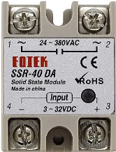
The SSR-40DA is a solid-state relay (SSR) designed for switching AC loads with high efficiency and reliability. Unlike mechanical relays, the SSR-40DA uses semiconductor components to perform switching operations, ensuring fast response times and long operational life. It is manufactured by Arduino and has the part ID "Nano."
This relay is commonly used in industrial automation, temperature control systems, motor control, and other applications requiring high-current AC switching. Its ability to handle up to 40A at 240V AC makes it suitable for heavy-duty applications.
Explore Projects Built with SSR-40DA
 Open Project in Cirkit Designer
 Open Project in Cirkit Designer
 Open Project in Cirkit Designer
 Open Project in Cirkit Designer
Explore Projects Built with SSR-40DA
Open Project in Cirkit DesignerOpen Project in Cirkit DesignerOpen Project in Cirkit DesignerOpen Project in Cirkit DesignerTechnical Specifications
Key Specifications
| Parameter | Value |
|---|---|
| Manufacturer | Arduino |
| Part ID | Nano |
| Input Control Voltage | 3-32V DC |
| Output Voltage Range | 24-380V AC |
| Maximum Output Current | 40A |
| Trigger Current | 7.5mA (minimum) |
| Isolation Voltage | ≥2500V AC |
| Switching Speed | ≤10ms |
| Operating Temperature | -30°C to +80°C |
| Mounting Type | Panel Mount |
Pin Configuration and Descriptions
The SSR-40DA has four terminals, as described below:
| Terminal Number | Label | Description |
|---|---|---|
| 1 | Input (+) | Positive terminal for the DC control signal (3-32V DC). |
| 2 | Input (-) | Negative terminal for the DC control signal (ground). |
| 3 | Output (L1) | AC load terminal 1 (connect to one side of the AC load). |
| 4 | Output (L2) | AC load terminal 2 (connect to the other side of the AC load or AC supply). |
Usage Instructions
How to Use the SSR-40DA in a Circuit
- Input Control Signal: Connect a DC control signal (3-32V DC) to the input terminals (1 and 2). Ensure the polarity is correct: the positive control voltage goes to terminal 1, and the ground goes to terminal 2.
- AC Load Connection: Connect the AC load to the output terminals (3 and 4). Terminal 3 (L1) is connected to one side of the load, and terminal 4 (L2) is connected to the other side of the load or the AC supply.
- Power Supply: Ensure the AC load voltage and current do not exceed the rated values (240V AC, 40A).
- Mounting: Secure the SSR-40DA to a heat sink or panel to dissipate heat effectively, especially for high-current applications.
Important Considerations and Best Practices
- Heat Dissipation: Use a heat sink or cooling fan to prevent overheating during operation. The SSR-40DA generates heat proportional to the load current.
- Snubber Circuit: For inductive loads (e.g., motors), use a snubber circuit to suppress voltage spikes and protect the relay.
- Isolation: Ensure proper electrical isolation between the control and load sides to prevent damage to the control circuit.
- Fuse Protection: Add a fuse or circuit breaker on the load side to protect against overcurrent conditions.
Example: Controlling the SSR-40DA with an Arduino UNO
The SSR-40DA can be controlled using an Arduino UNO to switch an AC load. Below is an example circuit and code:
Circuit Connections
- Connect the Arduino digital pin (e.g., pin 9) to the SSR-40DA input terminal 1 (+).
- Connect the SSR-40DA input terminal 2 (-) to the Arduino GND.
- Connect the AC load to the SSR-40DA output terminals (3 and 4) as described above.
Arduino Code
// Example code to control the SSR-40DA with an Arduino UNO
// This code toggles the relay ON and OFF every 2 seconds.

#define RELAY_PIN 9  // Define the Arduino pin connected to the SSR-40DA input

void setup() {
  pinMode(RELAY_PIN, OUTPUT);  // Set the relay pin as an output
}

void loop() {
  digitalWrite(RELAY_PIN, HIGH);  // Turn the relay ON
  delay(2000);                    // Wait for 2 seconds
  digitalWrite(RELAY_PIN, LOW);   // Turn the relay OFF
  delay(2000);                    // Wait for 2 seconds
}
Troubleshooting and FAQs
Common Issues and Solutions
Relay Not Switching the Load
- Cause: Insufficient input control voltage or incorrect polarity.
- Solution: Verify that the input control voltage is within the 3-32V DC range and that the polarity is correct.
Overheating
- Cause: High load current without proper heat dissipation.
- Solution: Attach a heat sink or cooling fan to the SSR-40DA.
Load Not Turning Off Completely
- Cause: Leakage current in the SSR.
- Solution: Ensure the load is compatible with the SSR and consider adding a resistor across the load to dissipate leakage current.
AC Load Flickering
- Cause: Insufficient input signal stability or noise.
- Solution: Use a stable DC control signal and add a capacitor to filter noise.
FAQs
Q1: Can the SSR-40DA switch DC loads?
A1: No, the SSR-40DA is designed specifically for AC loads. For DC loads, use a DC-specific solid-state relay.
Q2: What is the minimum load current required for proper operation?
A2: The SSR-40DA does not require a minimum load current, but ensure the load is within the rated range for optimal performance.
Q3: Can I use the SSR-40DA without a heat sink?
A3: It is not recommended for high-current applications. A heat sink is essential to prevent overheating and ensure reliable operation.
Q4: Is the SSR-40DA suitable for switching inductive loads?
A4: Yes, but a snubber circuit is recommended to protect the relay from voltage spikes caused by inductive loads.