Cirkit Designer Logo
Cirkit Designer
Your all-in-one circuit design IDE
Home / 
Component Documentation

How to Use XT30 Connector: Examples, Pinouts, and Specs

Image of XT30 Connector
Cirkit Designer LogoDesign with XT30 Connector in Cirkit Designer

Introduction

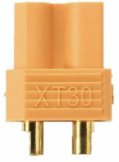
The XT30 Connector is a compact, lightweight, and durable electrical connector designed for high-current applications. It is widely used in remote-controlled (RC) vehicles, drones, and other battery-powered devices. The XT30 is known for its secure locking mechanism, which ensures a reliable connection even in environments with significant vibration or movement. With a current rating of up to 30A, it is ideal for applications requiring efficient power delivery in a small form factor.

Explore Projects Built with XT30 Connector

Use Cirkit Designer to design, explore, and prototype these projects online. Some projects support real-time simulation. Click "Open Project" to start designing instantly!
FTDI to UART Adapter with J26 Connector
Image of J26 CLOSEUP: A project utilizing XT30 Connector in a practical application
This circuit connects an FTDI USB-to-serial converter to a standard serial interface via a J26 connector. It facilitates serial communication by linking the ground, transmit, receive, data terminal ready, and request to send signals between the FTDI chip and the J26 connector.
Cirkit Designer LogoOpen Project in Cirkit Designer
Satellite-Based Timing and Navigation System with SDR and Atomic Clock Synchronization
Image of GPS 시스템 측정 구성도_Confirm: A project utilizing XT30 Connector in a practical application
This circuit appears to be a complex system involving power supply management, GPS and timing synchronization, and data communication. It includes a SI-TEX G1 Satellite Compass for GPS data, an XHTF1021 Atomic Rubidium Clock for precise timing, and Ettus USRP B200 units for software-defined radio communication. Power is supplied through various SMPS units and distributed via terminal blocks and DC jacks. Data communication is facilitated by Beelink MINI S12 N95 computers, RS232 splitters, and a 1000BASE-T Media Converter for network connectivity. RF Directional Couplers are used to interface antennas with the USRP units, and the entire system is likely contained within cases for protection and organization.
Cirkit Designer LogoOpen Project in Cirkit Designer
ESP32-CAM Module with USB to TTL Communication
Image of S: A project utilizing XT30 Connector in a practical application
This circuit connects an ESP32-CAM module to a USB to TTL module for serial communication and power supply. The ESP32-CAM's transmit (VOT) and receive (VOR) pins are connected to the USB to TTL's RXD and TXD pins respectively, enabling serial data exchange between the ESP32-CAM and a connected computer. Power (3V3 and 5V) and ground (GND) connections are also established between the two modules, ensuring the ESP32-CAM is powered and can communicate over USB.
Cirkit Designer LogoOpen Project in Cirkit Designer
Satellite Compass and Network-Integrated GPS Data Processing System
Image of GPS 시스템 측정 구성도_241016: A project utilizing XT30 Connector in a practical application
This circuit comprises a satellite compass, a mini PC, two GPS antennas, power supplies, a network switch, media converters, and an atomic rubidium clock. The satellite compass is powered by a triple output DC power supply and interfaces with an RS232 splitter for 1PPS signals. The mini PCs are connected to the USRP B200 devices via USB for data and power, and to media converters via Ethernet, which in turn connect to a network switch using fiber optic links. The antennas are connected to the USRP B200s through RF directional couplers, and the atomic clock provides a 1PPS input to the RS232 splitter.
Cirkit Designer LogoOpen Project in Cirkit Designer

Explore Projects Built with XT30 Connector

Use Cirkit Designer to design, explore, and prototype these projects online. Some projects support real-time simulation. Click "Open Project" to start designing instantly!
Image of J26 CLOSEUP: A project utilizing XT30 Connector in a practical application
FTDI to UART Adapter with J26 Connector
This circuit connects an FTDI USB-to-serial converter to a standard serial interface via a J26 connector. It facilitates serial communication by linking the ground, transmit, receive, data terminal ready, and request to send signals between the FTDI chip and the J26 connector.
Cirkit Designer LogoOpen Project in Cirkit Designer
Image of GPS 시스템 측정 구성도_Confirm: A project utilizing XT30 Connector in a practical application
Satellite-Based Timing and Navigation System with SDR and Atomic Clock Synchronization
This circuit appears to be a complex system involving power supply management, GPS and timing synchronization, and data communication. It includes a SI-TEX G1 Satellite Compass for GPS data, an XHTF1021 Atomic Rubidium Clock for precise timing, and Ettus USRP B200 units for software-defined radio communication. Power is supplied through various SMPS units and distributed via terminal blocks and DC jacks. Data communication is facilitated by Beelink MINI S12 N95 computers, RS232 splitters, and a 1000BASE-T Media Converter for network connectivity. RF Directional Couplers are used to interface antennas with the USRP units, and the entire system is likely contained within cases for protection and organization.
Cirkit Designer LogoOpen Project in Cirkit Designer
Image of S: A project utilizing XT30 Connector in a practical application
ESP32-CAM Module with USB to TTL Communication
This circuit connects an ESP32-CAM module to a USB to TTL module for serial communication and power supply. The ESP32-CAM's transmit (VOT) and receive (VOR) pins are connected to the USB to TTL's RXD and TXD pins respectively, enabling serial data exchange between the ESP32-CAM and a connected computer. Power (3V3 and 5V) and ground (GND) connections are also established between the two modules, ensuring the ESP32-CAM is powered and can communicate over USB.
Cirkit Designer LogoOpen Project in Cirkit Designer
Image of GPS 시스템 측정 구성도_241016: A project utilizing XT30 Connector in a practical application
Satellite Compass and Network-Integrated GPS Data Processing System
This circuit comprises a satellite compass, a mini PC, two GPS antennas, power supplies, a network switch, media converters, and an atomic rubidium clock. The satellite compass is powered by a triple output DC power supply and interfaces with an RS232 splitter for 1PPS signals. The mini PCs are connected to the USRP B200 devices via USB for data and power, and to media converters via Ethernet, which in turn connect to a network switch using fiber optic links. The antennas are connected to the USRP B200s through RF directional couplers, and the atomic clock provides a 1PPS input to the RS232 splitter.
Cirkit Designer LogoOpen Project in Cirkit Designer

Common Applications

  • RC vehicles (cars, boats, planes, etc.)
  • Drones and quadcopters
  • Battery packs for portable devices
  • Robotics and small-scale industrial equipment
  • DIY electronics projects requiring high-current connections

Technical Specifications

The XT30 Connector is designed to handle high currents while maintaining a compact size. Below are its key technical details:

Parameter Specification
Current Rating Up to 30A (continuous)
Voltage Rating Up to 500V DC
Contact Resistance ≤ 0.85 mΩ
Wire Gauge Support 16-20 AWG
Material (Contacts) Gold-plated brass
Material (Housing) Nylon (high-temperature resistant)
Operating Temperature -20°C to 120°C
Dimensions 13.5mm x 7.5mm x 15mm
Weight (per connector) ~2.3g

Pin Configuration and Descriptions

The XT30 Connector consists of two main pins: a positive (+) and a negative (-) terminal. These are clearly marked on the connector housing to prevent incorrect connections.

Pin Description
Positive Connects to the positive terminal of the power source or load.
Negative Connects to the negative terminal of the power source or load.

Usage Instructions

How to Use the XT30 Connector in a Circuit

  1. Prepare the Wires: Strip the insulation from the ends of the wires you intend to connect. Ensure the wire gauge is between 16 and 20 AWG for optimal performance.
  2. Solder the Wires:
    • Heat the soldering iron to the appropriate temperature (around 350°C for most solder types).
    • Tin the exposed wire ends by applying a small amount of solder to them.
    • Insert the tinned wire ends into the connector's solder cups (positive and negative terminals).
    • Apply heat and solder to secure the connection. Avoid overheating the connector housing.
  3. Inspect the Connection: Ensure the solder joints are clean, shiny, and free of excess solder. Verify that there are no short circuits between the positive and negative terminals.
  4. Assemble the Connector: Slide the heat-shrink tubing (if used) over the soldered connections and apply heat to shrink it securely in place.
  5. Connect to the Circuit: Plug the XT30 connectors together, ensuring the positive and negative terminals are correctly aligned.

Important Considerations and Best Practices

  • Polarity: Always double-check the polarity markings on the connector to avoid reverse connections, which can damage your circuit.
  • Soldering: Use a high-quality soldering iron and solder to ensure reliable connections. Avoid cold solder joints, as they can lead to poor conductivity or failure.
  • Heat Management: Do not overheat the connector housing during soldering, as excessive heat can deform the nylon material.
  • Secure Fit: Ensure the connectors are fully mated and locked to prevent accidental disconnection during operation.
  • Wire Gauge: Use the recommended wire gauge (16-20 AWG) to handle the rated current without overheating.

Example: Connecting an XT30 to an Arduino UNO

While the XT30 is not directly connected to an Arduino UNO, it can be used to supply power to the Arduino via a battery pack. Below is an example of how to use the XT30 in such a setup:

  1. Connect the XT30 to a battery pack (e.g., a 7.4V LiPo battery).
  2. Use a voltage regulator module (e.g., LM7805) to step down the voltage to 5V for the Arduino UNO.
  3. Connect the output of the voltage regulator to the Arduino's 5V and GND pins.
// Example Arduino code to read battery voltage via an analog pin
const int batteryPin = A0; // Analog pin connected to the voltage divider
float voltage = 0.0;

void setup() {
  Serial.begin(9600); // Initialize serial communication
}

void loop() {
  int sensorValue = analogRead(batteryPin); // Read the analog value
  voltage = sensorValue * (5.0 / 1023.0);   // Convert to voltage
  Serial.print("Battery Voltage: ");
  Serial.print(voltage);
  Serial.println(" V");
  delay(1000); // Wait for 1 second
}

Note: Use a voltage divider circuit to scale down the battery voltage to a safe range (0-5V) for the Arduino's analog input.

Troubleshooting and FAQs

Common Issues

  1. Loose Connections:

    • Cause: Incomplete mating of the connectors or poor soldering.
    • Solution: Ensure the connectors are fully locked and inspect solder joints for quality.
  2. Overheating:

    • Cause: Exceeding the current rating or using an incorrect wire gauge.
    • Solution: Use wires within the recommended gauge (16-20 AWG) and ensure the current does not exceed 30A.
  3. Melted Housing:

    • Cause: Excessive heat during soldering.
    • Solution: Use a temperature-controlled soldering iron and limit soldering time to a few seconds per joint.
  4. Reverse Polarity Connection:

    • Cause: Incorrect wiring or connection.
    • Solution: Double-check the polarity markings on the connector before connecting.

FAQs

Q1: Can the XT30 Connector handle more than 30A?
A1: No, the XT30 is rated for a maximum continuous current of 30A. Exceeding this limit can cause overheating and damage.

Q2: Is the XT30 Connector waterproof?
A2: No, the XT30 is not waterproof. For outdoor or wet environments, consider using additional waterproofing measures.

Q3: Can I use the XT30 Connector with thicker wires (e.g., 14 AWG)?
A3: The XT30 is designed for 16-20 AWG wires. Using thicker wires may require modification, but this is not recommended as it can compromise the connection quality.

Q4: How do I disconnect the XT30 Connector?
A4: Firmly grip both connectors and pull them apart. Avoid pulling on the wires to prevent damage.

By following this documentation, you can effectively use the XT30 Connector in your projects while ensuring safety and reliability.