Cirkit Designer Logo
Cirkit Designer
Your all-in-one circuit design IDE
Home / 
Component Documentation

How to Use RFM69 Breakout (915MHz): Examples, Pinouts, and Specs

Image of RFM69 Breakout (915MHz)
Cirkit Designer LogoDesign with RFM69 Breakout (915MHz) in Cirkit Designer

Introduction

The RFM69 Breakout (915MHz) is a versatile and powerful low-power wireless transceiver module designed for operation in the 915MHz ISM (Industrial, Scientific, and Medical) frequency band. It is widely used in a variety of applications such as wireless sensor networks, home automation, remote control systems, and other projects that require reliable wireless communication over medium to long distances.

Explore Projects Built with RFM69 Breakout (915MHz)

Use Cirkit Designer to design, explore, and prototype these projects online. Some projects support real-time simulation. Click "Open Project" to start designing instantly!
Dual-Mode LoRa and GSM Communication Device with ESP32
Image of modul gateway: A project utilizing RFM69 Breakout (915MHz) in a practical application
This circuit features an ESP32 Devkit V1 microcontroller interfaced with an RFM95 LoRa transceiver module for long-range communication and a SIM800L GSM module for cellular connectivity. Two LM2596 step-down modules are used to regulate the 12V battery voltage down to 3.3V required by the ESP32, RFM95, and SIM800L. The ESP32 facilitates data exchange between the RFM95 and SIM800L, enabling the system to send/receive data over both LoRa and GSM networks.
Cirkit Designer LogoOpen Project in Cirkit Designer
Arduino Nano-Based GPS Tracker with GSM and LoRa Communication
Image of Electromagnetic Sensor: A project utilizing RFM69 Breakout (915MHz) in a practical application
This circuit features an Arduino Nano microcontroller interfaced with an RFM95 LoRa transceiver module for long-range communication, a SIM800L GSM module for cellular connectivity, and a GPS NEO 6M module for location tracking. The Arduino Nano also connects to an inductive sensor for proximity or metal detection. The circuit is designed for applications requiring wireless communication, location tracking, and proximity sensing, with the Arduino Nano serving as the central processing unit.
Cirkit Designer LogoOpen Project in Cirkit Designer
ESP32-Based RF Communication System with 433 MHz Modules
Image of 433 mhz: A project utilizing RFM69 Breakout (915MHz) in a practical application
This circuit comprises an ESP32 microcontroller connected to a 433 MHz RF transmitter and receiver pair. The ESP32 is programmed to receive and decode RF signals through the receiver module, as well as send RF signals via the transmitter module. Additionally, the ESP32 can communicate with a Bluetooth device to exchange commands and data, and it uses an LED for status indication.
Cirkit Designer LogoOpen Project in Cirkit Designer
Arduino UNO with 433MHz RF Module for Wireless Communication
Image of Receiver: A project utilizing RFM69 Breakout (915MHz) in a practical application
This circuit consists of an Arduino UNO connected to an RXN433MHz radio frequency module. The Arduino provides 5V power and ground to the RF module and is configured to communicate with it via digital pin D11. Additionally, a multimeter is connected with alligator clip cables to measure the voltage supplied to the RF module.
Cirkit Designer LogoOpen Project in Cirkit Designer

Explore Projects Built with RFM69 Breakout (915MHz)

Use Cirkit Designer to design, explore, and prototype these projects online. Some projects support real-time simulation. Click "Open Project" to start designing instantly!
Image of modul gateway: A project utilizing RFM69 Breakout (915MHz) in a practical application
Dual-Mode LoRa and GSM Communication Device with ESP32
This circuit features an ESP32 Devkit V1 microcontroller interfaced with an RFM95 LoRa transceiver module for long-range communication and a SIM800L GSM module for cellular connectivity. Two LM2596 step-down modules are used to regulate the 12V battery voltage down to 3.3V required by the ESP32, RFM95, and SIM800L. The ESP32 facilitates data exchange between the RFM95 and SIM800L, enabling the system to send/receive data over both LoRa and GSM networks.
Cirkit Designer LogoOpen Project in Cirkit Designer
Image of Electromagnetic Sensor: A project utilizing RFM69 Breakout (915MHz) in a practical application
Arduino Nano-Based GPS Tracker with GSM and LoRa Communication
This circuit features an Arduino Nano microcontroller interfaced with an RFM95 LoRa transceiver module for long-range communication, a SIM800L GSM module for cellular connectivity, and a GPS NEO 6M module for location tracking. The Arduino Nano also connects to an inductive sensor for proximity or metal detection. The circuit is designed for applications requiring wireless communication, location tracking, and proximity sensing, with the Arduino Nano serving as the central processing unit.
Cirkit Designer LogoOpen Project in Cirkit Designer
Image of 433 mhz: A project utilizing RFM69 Breakout (915MHz) in a practical application
ESP32-Based RF Communication System with 433 MHz Modules
This circuit comprises an ESP32 microcontroller connected to a 433 MHz RF transmitter and receiver pair. The ESP32 is programmed to receive and decode RF signals through the receiver module, as well as send RF signals via the transmitter module. Additionally, the ESP32 can communicate with a Bluetooth device to exchange commands and data, and it uses an LED for status indication.
Cirkit Designer LogoOpen Project in Cirkit Designer
Image of Receiver: A project utilizing RFM69 Breakout (915MHz) in a practical application
Arduino UNO with 433MHz RF Module for Wireless Communication
This circuit consists of an Arduino UNO connected to an RXN433MHz radio frequency module. The Arduino provides 5V power and ground to the RF module and is configured to communicate with it via digital pin D11. Additionally, a multimeter is connected with alligator clip cables to measure the voltage supplied to the RF module.
Cirkit Designer LogoOpen Project in Cirkit Designer

Technical Specifications

Key Features

  • Frequency Range: 915 MHz ISM Band
  • Modulation Techniques: FSK, GFSK, MSK, GMSK, OOK
  • Output Power: +13 to +20 dBm up to 100 mW Power Output Capability
  • Sensitivity: down to -120 dBm at 1.2 kbps
  • Data Rate: 1.2 to 300 kbps
  • Supply Voltage: 1.8 - 3.6 V
  • Current Consumption: 16 mA (transmit at +13 dBm), 1.25 mA (receive mode), 0.1 µA (sleep mode)
  • Digital RSSI function
  • Temperature Sensor and 8-bit ADC
  • Packet engine with CRC, AES-128 encryption, and 66-byte FIFO
  • Built-in Sync Word recognition
  • 2-FSK, 4-FSK, GFSK, and OOK modulations
  • Automatic Frequency Control (AFC)
  • Packet engine with CRC, AES-128 encryption, and 66-byte FIFO

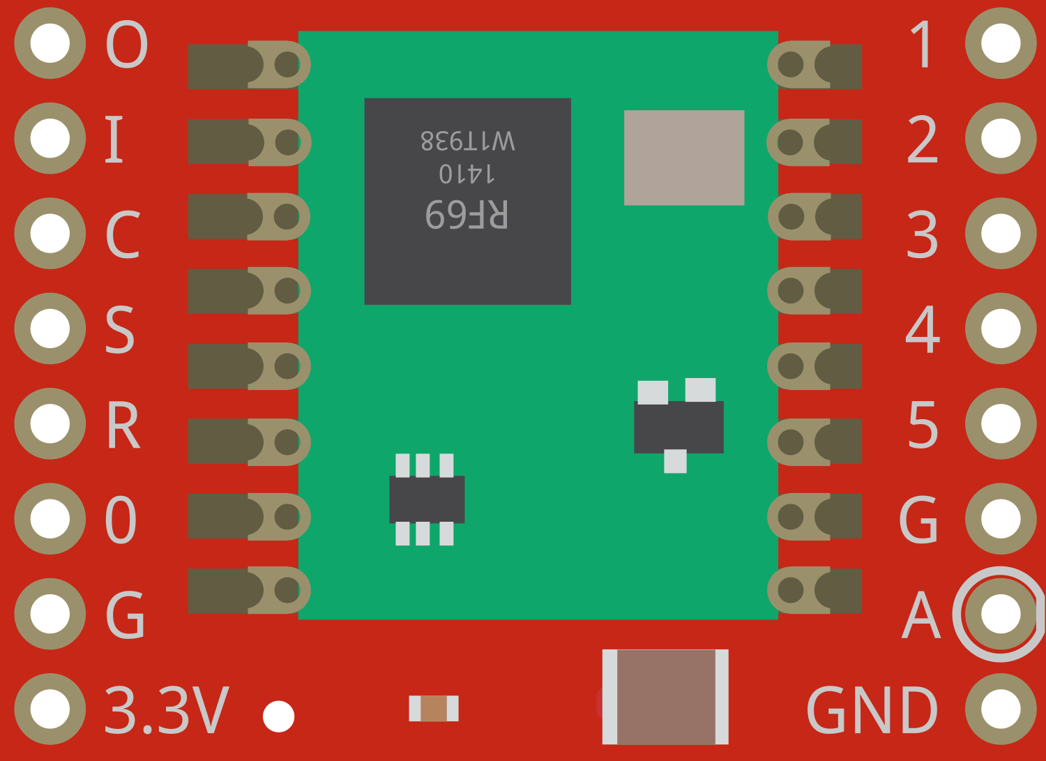
Pin Configuration and Descriptions

Pin Number Name Description
1 GND Ground connection
2 VCC Power supply (1.8V - 3.6V)
3 DIO0 Digital I/O, configurable for interrupt signaling
4 DIO1 Digital I/O, configurable for interrupt signaling
5 DIO2 Digital I/O, configurable for interrupt signaling
6 DIO3 Digital I/O, configurable for interrupt signaling
7 DIO4 Digital I/O, configurable for interrupt signaling
8 DIO5 Digital I/O, configurable for interrupt signaling
9 SCK Serial Clock for SPI interface
10 MISO Master In Slave Out for SPI interface
11 MOSI Master Out Slave In for SPI interface
12 NSS Chip Select for SPI interface
13 RESET Reset pin
14 ANT Antenna connection

Usage Instructions

Basic Setup

  1. Power Supply: Connect a stable power supply (1.8V - 3.6V) to the VCC pin and ground to the GND pin.
  2. SPI Interface: Connect the SCK, MISO, MOSI, and NSS pins to your microcontroller's corresponding SPI pins.
  3. Antenna: Attach an appropriate 915MHz antenna to the ANT pin for optimal range and performance.
  4. Interrupts (Optional): DIO0-DIO5 can be used for various interrupt-driven functions. Connect these to the microcontroller's interrupt-capable GPIO pins if needed.

Communication with Arduino UNO

To communicate with an Arduino UNO, you'll need to connect the RFM69's SPI pins to the corresponding pins on the Arduino:

  • RFM69 SCK to Arduino Pin 13
  • RFM69 MISO to Arduino Pin 12
  • RFM69 MOSI to Arduino Pin 11
  • RFM69 NSS to a free digital pin (e.g., Pin 10)
  • RFM69 DIO0 to another free digital pin (e.g., Pin 2)

Arduino Code Example

Below is a simple example of initializing the RFM69 module with an Arduino UNO. This code assumes you have installed the appropriate RFM69 library.

#include <RFM69.h>

#define NETWORKID     0   // Must be the same for all nodes
#define NODEID        1   // Unique for each node
#define RECEIVER      2   // Receiver node ID
#define FREQUENCY     RF69_915MHZ
#define ENCRYPTKEY    "sampleEncryptKey" // Use the same 16-byte key for all nodes
#define RFM69_CS      10  // RFM69 chip select pin
#define RFM69_IRQ     2   // RFM69 interrupt pin
#define RFM69_IRQN    digitalPinToInterrupt(RFM69_IRQ)

RFM69 radio(RFM69_CS, RFM69_IRQ, true);

void setup() {
  Serial.begin(9600);
  while (!Serial); // Wait until serial console is open, remove if not tethered to computer

  radio.initialize(FREQUENCY, NODEID, NETWORKID);
  radio.encrypt(ENCRYPTKEY);
  radio.setHighPower(); // Only for RFM69HW & HW-C
  Serial.println("RFM69 module initialized");
}

void loop() {
  // Your code to send or receive messages
}

Ensure that you have the correct library installed and that the RFM69_CS and RFM69_IRQ pins are defined according to your wiring.

Troubleshooting and FAQs

Common Issues

  • No Communication: Ensure that the antenna is properly connected and that the power supply is within the specified range.
  • Short Range: Check the antenna and make sure there are no obstructions or interference in the operating environment.
  • SPI Issues: Verify that the SPI connections are correct and that there are no soldering issues on the breakout board.

FAQs

Q: Can I use the RFM69 module with a 3.3V Arduino? A: Yes, the RFM69 can be powered with 3.3V, which is compatible with 3.3V Arduinos.

Q: How can I increase the range of the RFM69 module? A: Use a high-quality antenna, reduce the data rate, increase the transmit power, and ensure there are no obstructions or sources of interference.

Q: Is the RFM69 module compatible with other RFM69-based networks? A: Yes, as long as they operate on the same frequency and network settings (network ID, encryption key) are the same.

For further assistance, consult the RFM69 datasheet and the library documentation for advanced configurations and troubleshooting tips.