Cirkit Designer Logo
Cirkit Designer
Your all-in-one circuit design IDE
Home / 
Component Documentation

How to Use HW-532 Mosfet: Examples, Pinouts, and Specs

Image of HW-532 Mosfet
Cirkit Designer LogoDesign with HW-532 Mosfet in Cirkit Designer

Introduction

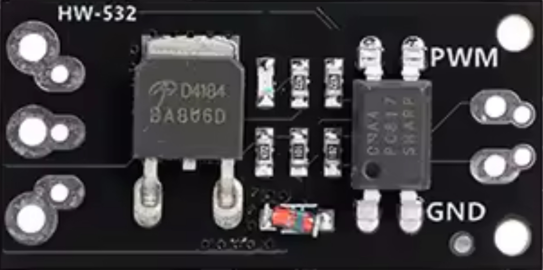
The HW-532 is a Metal-Oxide-Semiconductor Field-Effect Transistor (MOSFET) designed for efficient switching and signal amplification. It is characterized by its low on-resistance and high-speed switching capabilities, making it an ideal choice for applications requiring precise control of current and voltage. The HW-532 is commonly used in power management circuits, motor drivers, LED drivers, and signal processing systems.

Explore Projects Built with HW-532 Mosfet

Use Cirkit Designer to design, explore, and prototype these projects online. Some projects support real-time simulation. Click "Open Project" to start designing instantly!
ESP8266-Controlled Wireless EV Charging System with RFID Authentication
Image of Minor Project: A project utilizing HW-532 Mosfet in a practical application
This circuit appears to be a wireless charging system with RFID access control, powered by an AC supply that is rectified and regulated. It includes an ESP8266 microcontroller for managing the charging process and displaying status information on an OLED display. The RFID-RC522 module is used to authorize the charging process, and a MOSFET is likely used to control the power to the charging coil.
Cirkit Designer LogoOpen Project in Cirkit Designer
Pixhawk-Controlled Solenoid Driver with Voltage Regulation
Image of solenoid control circuit: A project utilizing HW-532 Mosfet in a practical application
This circuit uses an LM393 comparator to drive an IRFZ44N MOSFET based on the comparison between two input signals from a pixhawk 2.4.8 flight controller. The MOSFET switches a solenoid, with a diode for back EMF protection, and the system is powered by a Lipo battery with voltage regulation provided by a step-up boost converter and a step-down voltage regulator to ensure stable operation. A resistor is connected to the gate of the MOSFET for proper biasing.
Cirkit Designer LogoOpen Project in Cirkit Designer
STM32 Nucleo-Controlled Solenoid Actuation System
Image of stm32 braile: A project utilizing HW-532 Mosfet in a practical application
This circuit appears to be a microcontroller-driven array of push-pull solenoids with flyback diodes for protection. The STM32 Nucleo F303RE microcontroller's GPIO pins are connected to the gates of several nMOS transistors, which act as switches to control the current flow to the solenoids. A pushbutton with a pull-up resistor is also interfaced with the microcontroller for user input, and the power supply is connected to the solenoids with ground return paths through the nMOS transistors.
Cirkit Designer LogoOpen Project in Cirkit Designer
Battery-Powered nRF52840 and HT-RA62 Communication Module
Image of NRF52840+HT-RA62: A project utilizing HW-532 Mosfet in a practical application
This circuit is a wireless communication system powered by a 18650 Li-ion battery, featuring an nRF52840 ProMicro microcontroller and an HT-RA62 transceiver module. The nRF52840 handles the control logic and interfaces with the HT-RA62 for data transmission, while the battery provides the necessary power for the entire setup.
Cirkit Designer LogoOpen Project in Cirkit Designer

Explore Projects Built with HW-532 Mosfet

Use Cirkit Designer to design, explore, and prototype these projects online. Some projects support real-time simulation. Click "Open Project" to start designing instantly!
Image of Minor Project: A project utilizing HW-532 Mosfet in a practical application
ESP8266-Controlled Wireless EV Charging System with RFID Authentication
This circuit appears to be a wireless charging system with RFID access control, powered by an AC supply that is rectified and regulated. It includes an ESP8266 microcontroller for managing the charging process and displaying status information on an OLED display. The RFID-RC522 module is used to authorize the charging process, and a MOSFET is likely used to control the power to the charging coil.
Cirkit Designer LogoOpen Project in Cirkit Designer
Image of solenoid control circuit: A project utilizing HW-532 Mosfet in a practical application
Pixhawk-Controlled Solenoid Driver with Voltage Regulation
This circuit uses an LM393 comparator to drive an IRFZ44N MOSFET based on the comparison between two input signals from a pixhawk 2.4.8 flight controller. The MOSFET switches a solenoid, with a diode for back EMF protection, and the system is powered by a Lipo battery with voltage regulation provided by a step-up boost converter and a step-down voltage regulator to ensure stable operation. A resistor is connected to the gate of the MOSFET for proper biasing.
Cirkit Designer LogoOpen Project in Cirkit Designer
Image of stm32 braile: A project utilizing HW-532 Mosfet in a practical application
STM32 Nucleo-Controlled Solenoid Actuation System
This circuit appears to be a microcontroller-driven array of push-pull solenoids with flyback diodes for protection. The STM32 Nucleo F303RE microcontroller's GPIO pins are connected to the gates of several nMOS transistors, which act as switches to control the current flow to the solenoids. A pushbutton with a pull-up resistor is also interfaced with the microcontroller for user input, and the power supply is connected to the solenoids with ground return paths through the nMOS transistors.
Cirkit Designer LogoOpen Project in Cirkit Designer
Image of NRF52840+HT-RA62: A project utilizing HW-532 Mosfet in a practical application
Battery-Powered nRF52840 and HT-RA62 Communication Module
This circuit is a wireless communication system powered by a 18650 Li-ion battery, featuring an nRF52840 ProMicro microcontroller and an HT-RA62 transceiver module. The nRF52840 handles the control logic and interfaces with the HT-RA62 for data transmission, while the battery provides the necessary power for the entire setup.
Cirkit Designer LogoOpen Project in Cirkit Designer

Common Applications:

  • Power supply circuits
  • Motor control and drivers
  • LED dimming and control
  • Signal amplification in audio and RF systems
  • Battery management systems

Technical Specifications

Key Specifications:

Parameter Value
Type N-Channel MOSFET
Maximum Drain-Source Voltage (VDS) 60V
Maximum Gate-Source Voltage (VGS) ±20V
Continuous Drain Current (ID) 30A
Pulsed Drain Current (ID,pulse) 120A
On-Resistance (RDS(on)) 0.015Ω (at VGS = 10V)
Gate Threshold Voltage (VGS(th)) 2V - 4V
Power Dissipation (PD) 50W
Operating Temperature -55°C to +175°C
Package Type TO-220

Pin Configuration:

The HW-532 MOSFET is typically available in a TO-220 package with three pins. The pinout is as follows:

Pin Number Name Description
1 Gate Controls the MOSFET's switching state. A voltage applied here determines whether the MOSFET is on or off.
2 Drain The main current-carrying terminal. Current flows from the drain to the source when the MOSFET is on.
3 Source The terminal through which current exits the MOSFET.

Usage Instructions

How to Use the HW-532 in a Circuit:

  1. Gate Control: Connect the gate pin to a control signal (e.g., from a microcontroller or a signal generator). Ensure the gate voltage (VGS) is within the specified range (typically 10V for full switching).
  2. Drain-Source Connection: Connect the load (e.g., motor, LED, or resistor) between the drain pin and the positive supply voltage. The source pin should be connected to ground.
  3. Gate Resistor: Use a resistor (typically 10Ω to 100Ω) in series with the gate to limit inrush current and prevent damage to the MOSFET.
  4. Flyback Diode: For inductive loads (e.g., motors or relays), connect a flyback diode across the load to protect the MOSFET from voltage spikes.
  5. Heat Dissipation: Attach a heatsink to the MOSFET if the power dissipation exceeds safe limits.

Example Circuit with Arduino UNO:

The HW-532 can be used to control a DC motor with an Arduino UNO. Below is an example circuit and code:

Circuit Connections:

  • Gate: Connect to Arduino digital pin 9 through a 100Ω resistor.
  • Drain: Connect to one terminal of the motor.
  • Source: Connect to ground.
  • Motor: Connect the other terminal to the positive supply voltage (e.g., 12V).
  • Flyback Diode: Place a diode (e.g., 1N4007) across the motor terminals, with the cathode connected to the positive supply.

Arduino Code:

// Define the pin connected to the MOSFET gate
const int mosfetGatePin = 9;

void setup() {
  // Set the MOSFET gate pin as an output
  pinMode(mosfetGatePin, OUTPUT);
}

void loop() {
  // Turn the MOSFET on (motor runs)
  digitalWrite(mosfetGatePin, HIGH);
  delay(1000); // Keep the motor on for 1 second

  // Turn the MOSFET off (motor stops)
  digitalWrite(mosfetGatePin, LOW);
  delay(1000); // Keep the motor off for 1 second
}

Important Considerations:

  • Ensure the gate voltage (VGS) is sufficient to fully turn on the MOSFET (typically 10V for the HW-532).
  • Avoid exceeding the maximum voltage and current ratings to prevent damage.
  • Use proper heat dissipation methods, such as heatsinks or active cooling, for high-power applications.
  • For PWM (Pulse Width Modulation) control, ensure the switching frequency is within the MOSFET's capabilities.

Troubleshooting and FAQs

Common Issues and Solutions:

  1. MOSFET Overheating:

    • Cause: Insufficient heat dissipation or excessive current.
    • Solution: Attach a heatsink or reduce the load current.
  2. MOSFET Not Switching On:

    • Cause: Gate voltage (VGS) is too low.
    • Solution: Ensure the gate voltage is at least 10V for full switching.
  3. Load Not Operating Properly:

    • Cause: Incorrect wiring or insufficient power supply.
    • Solution: Double-check the circuit connections and ensure the power supply meets the load's requirements.
  4. Voltage Spikes Damaging the MOSFET:

    • Cause: Inductive loads generating back EMF.
    • Solution: Add a flyback diode across the load.

FAQs:

Q1: Can the HW-532 be used for high-frequency switching?
A1: Yes, the HW-532 supports high-speed switching, but ensure the gate driver can supply sufficient current for fast transitions.

Q2: What is the maximum PWM frequency for the HW-532?
A2: The maximum frequency depends on the gate capacitance and the gate driver. Typically, it can handle frequencies up to several hundred kHz with an appropriate driver.

Q3: Can I use the HW-532 with a 3.3V microcontroller?
A3: The HW-532 requires a gate voltage of at least 10V for full switching. Use a gate driver or level shifter if controlling it with a 3.3V microcontroller.

Q4: Is the HW-532 suitable for AC loads?
A4: The HW-532 is designed for DC applications. For AC loads, consider using a TRIAC or an IGBT.