How to Use Mini Analog Thumbstick: Examples, Pinouts, and Specs

Introduction
The Mini Analog Thumbstick by PiHut is a compact joystick designed for precise input control in gaming controllers, robotics, and other interactive devices. It provides two analog outputs (X and Y axes) and a digital button press when the joystick is pushed down. This versatile component is ideal for applications requiring smooth directional control, such as remote-controlled vehicles, robotic arms, and gaming interfaces.
Explore Projects Built with Mini Analog Thumbstick
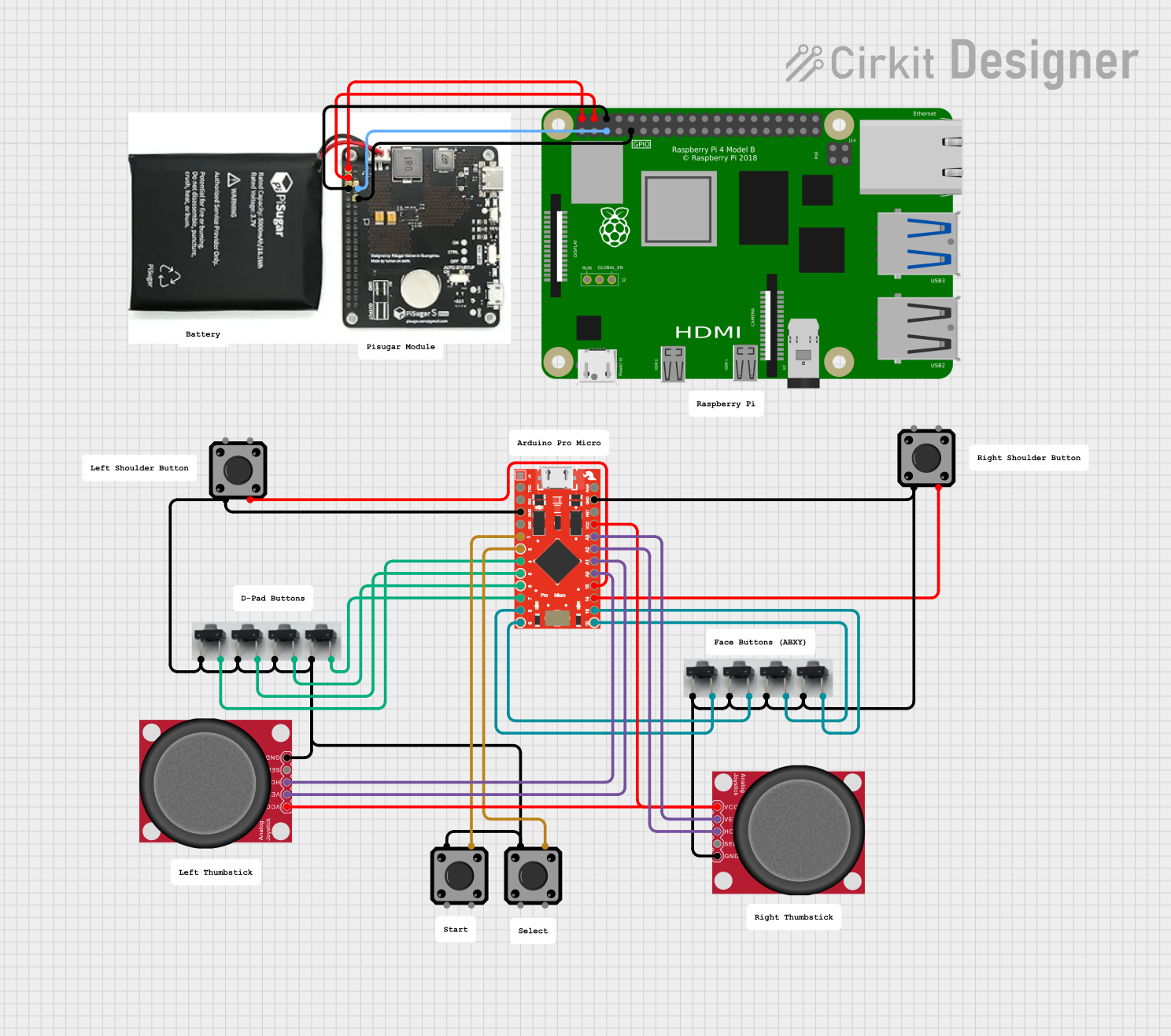


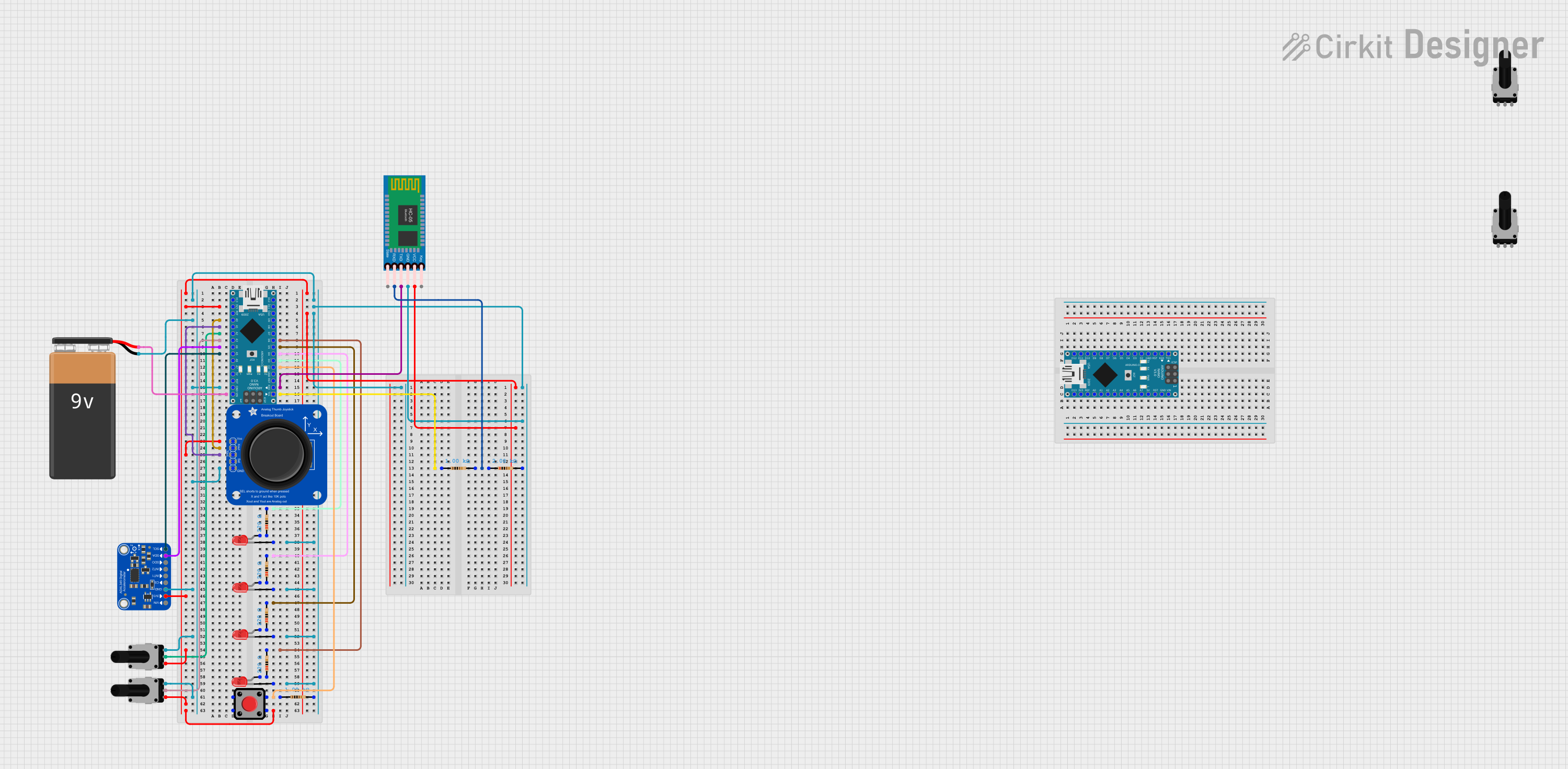
Explore Projects Built with Mini Analog Thumbstick
Common Applications
- Gaming controllers for directional input
- Robotics for movement control
- DIY projects requiring analog input
- Remote-controlled devices
- Interactive user interfaces
Technical Specifications
Key Technical Details
- Manufacturer: PiHut
- Operating Voltage: 3.3V to 5V
- Output Type: Analog (X and Y axes), Digital (button press)
- X/Y Axis Range: 0V to VCC (proportional to joystick position)
- Button Type: Momentary push-button (active low)
- Dimensions: 26mm x 26mm x 20mm (excluding pins)
- Mounting: PCB through-hole
Pin Configuration and Descriptions
The Mini Analog Thumbstick has 5 pins, as detailed in the table below:
| Pin | Name | Description |
|---|---|---|
| 1 | GND | Ground connection for the thumbstick. |
| 2 | +VCC | Power supply input (3.3V to 5V). |
| 3 | VRx | Analog output for the X-axis (horizontal movement). |
| 4 | VRy | Analog output for the Y-axis (vertical movement). |
| 5 | SW | Digital output for the push-button (active low, connects to GND when pressed). |
Usage Instructions
How to Use the Component in a Circuit
Power the Thumbstick:
Connect the +VCC pin to a 3.3V or 5V power source and the GND pin to ground.Read Analog Outputs:
- Connect the VRx pin to an analog input pin on your microcontroller to read horizontal movement.
- Connect the VRy pin to another analog input pin to read vertical movement.
- The voltage on these pins will vary between 0V and VCC, depending on the joystick's position.
Read the Button Press:
- Connect the SW pin to a digital input pin on your microcontroller.
- Use a pull-up resistor (internal or external) to ensure the pin reads HIGH when the button is not pressed.
- When the button is pressed, the pin will read LOW.
Important Considerations and Best Practices
- Debouncing: When using the push-button, implement software debouncing to avoid false triggers.
- Voltage Compatibility: Ensure your microcontroller's analog input pins can handle the voltage range (3.3V or 5V).
- Calibration: For precise control, calibrate the joystick's analog outputs to account for any offsets or variations.
- Mechanical Stress: Avoid applying excessive force to the joystick to prevent damage.
Example Code for Arduino UNO
Below is an example of how to interface the Mini Analog Thumbstick with an Arduino UNO:
// Pin definitions
const int VRxPin = A0; // X-axis connected to analog pin A0
const int VRyPin = A1; // Y-axis connected to analog pin A1
const int SWPin = 2;   // Button connected to digital pin 2

void setup() {
  // Initialize serial communication for debugging
  Serial.begin(9600);

  // Configure the button pin as input with internal pull-up resistor
  pinMode(SWPin, INPUT_PULLUP);
}

void loop() {
  // Read the X and Y axis values (0 to 1023)
  int xValue = analogRead(VRxPin);
  int yValue = analogRead(VRyPin);

  // Read the button state (LOW when pressed, HIGH otherwise)
  int buttonState = digitalRead(SWPin);

  // Print the values to the Serial Monitor
  Serial.print("X: ");
  Serial.print(xValue);
  Serial.print(" | Y: ");
  Serial.print(yValue);
  Serial.print(" | Button: ");
  Serial.println(buttonState == LOW ? "Pressed" : "Released");

  // Add a small delay for stability
  delay(100);
}
Notes:
- The analog values for the X and Y axes will range from approximately 0 to 1023 on the Arduino UNO, corresponding to 0V to 5V.
- The button state will read
LOWwhen pressed andHIGHwhen released due to the pull-up resistor.
Troubleshooting and FAQs
Common Issues and Solutions
No Output from the Joystick
- Cause: Incorrect wiring or loose connections.
- Solution: Double-check all connections, ensuring the power supply is properly connected to +VCC and GND.
Analog Values Are Not Stable
- Cause: Electrical noise or poor power supply.
- Solution: Use decoupling capacitors (e.g., 0.1µF) between +VCC and GND to filter noise.
Button Not Responding
- Cause: Missing pull-up resistor or incorrect pin configuration.
- Solution: Ensure the SW pin is configured as an input with a pull-up resistor (internal or external).
Joystick Outputs Incorrect Range
- Cause: Calibration issue or damaged component.
- Solution: Calibrate the joystick in software to map the raw analog values to the expected range.
FAQs
Q1: Can I use the Mini Analog Thumbstick with a 3.3V microcontroller like the ESP32?
A1: Yes, the thumbstick operates at both 3.3V and 5V. Ensure the microcontroller's analog pins are compatible with the voltage range.
Q2: How do I mount the thumbstick on a PCB?
A2: The thumbstick has through-hole pins for easy soldering onto a PCB. Ensure proper alignment and secure solder joints.
Q3: Can I use the thumbstick for digital-only applications?
A3: While the thumbstick is primarily designed for analog input, you can use the push-button for digital input in such applications.
Q4: What is the lifespan of the joystick?
A4: The Mini Analog Thumbstick is designed for durability, but its lifespan depends on usage conditions. Avoid excessive force to prolong its life.